Gocator Line Profile Sensors: User Manual
Gocator Web Interface • 104
The following table provides quick references for specific goals that you can achieve from the panels in
the Scan page.
Goal Reference
Select a trigger source that is appropriate for the application. Triggers (page 105)
Ensure that camera exposure is appropriate for scan data acquisition. Exposure (page 117)
Find the right balance between data quality, speed, and CPU utilization. Active Area (page 112)
Exposure (page 117)
Job File Structure (page 356)
Specify mounting orientations. Layout (page 84)
Calibrate the system so that scan data can be aligned to a common reference and
values can be correctly scaled in the axis of motion.
Aligning Sensors (page 126)
Set up the part detection logic to create discrete objects from scan data. Part Detection (page 137)
Specify smoothing, gap-filling, and resampling parameters to remove effects of
occlusions.
Filters (page 130)
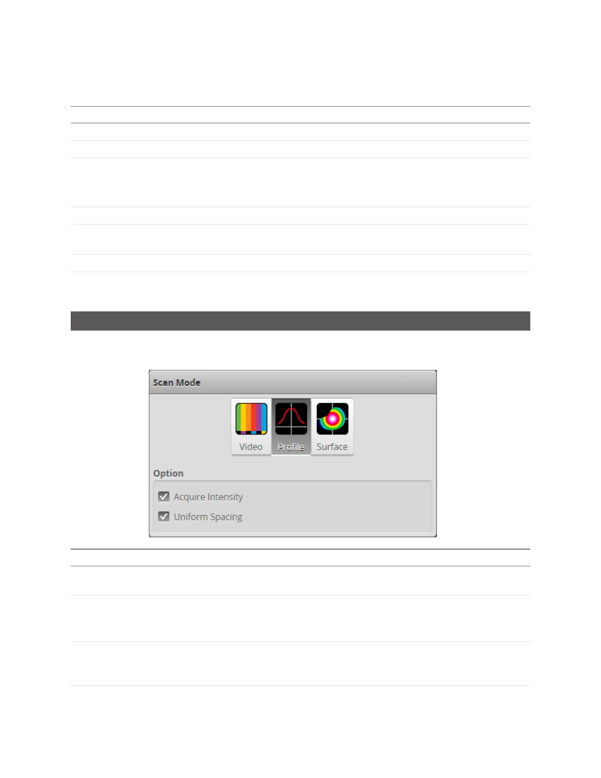
Scan Modes
The Gocator web interface supports a video mode and one or more data acquisition modes. The scan
mode can be selected in the Scan Mode panel.
Mode and Option Description
Video Outputs video images from the Gocator. This mode is useful for configuring exposure time and
troubleshooting stray light or ambient light problems.
Profile
Outputs profiles and performs profile measurements.
Video images are processed internally to produce laser profiles and cross-sectional
measurements.
Surface
Outputs 3D point clouds and performs surface measurements. The sensor uses various
methods to generate a surface (see Surface Generation on page 134). Part detection can be
enabled on a surface to identify discrete parts (Part Detection on page 137).