Gocator Line Profile Sensors: User Manual
Getting Started • 37
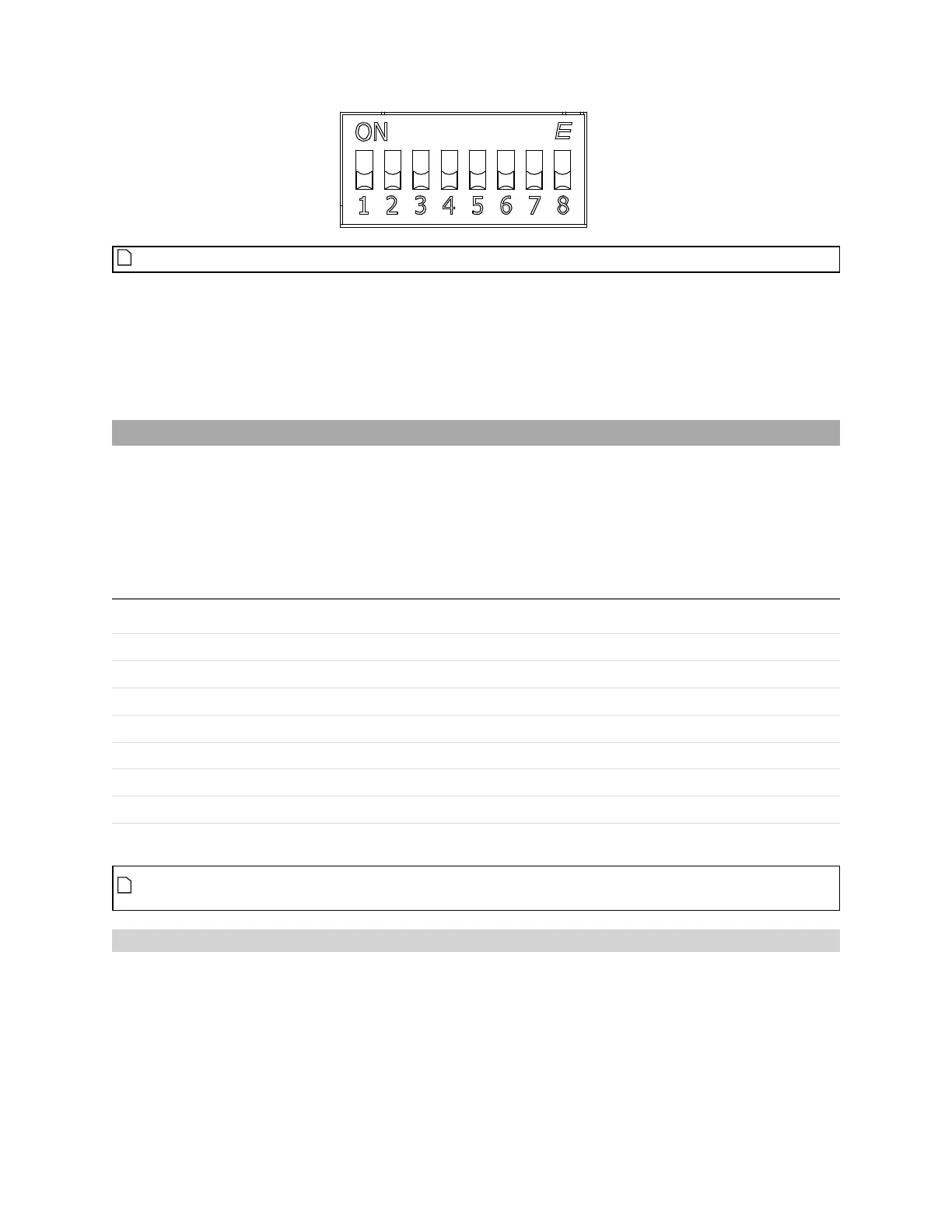
Switches 5 to 8 are reserved for future use.
This section describes how to set the DIP switches on Master 810 to do the following:
l Set the divider so that the quadrature frequency of the connected encoder is compatible with the
Master.
l Set the debounce period to accommodate faster encoders.
Setting the Divider
To set the divider, you use switches 1 to 3. To determine which divider to use, use the following formula:
Output Quadrature Frequency = Input Quadrature Frequency / Divider
In the formula, use the quadrature frequency of the encoder (for more information, see Encoder
Quadrature Frequency below) and a divider from the following table so that the Output Quadrature
Frequency is no more than 300 kHz.
Divider Switch 1 Switch 2 Switch 3
1 OFF OFF OFF
2 ON OFF OFF
4 OFF ON OFF
8 ON ON OFF
16 OFF OFF ON
32 ON OFF ON
64 OFF ON ON
128 ON ON ON
The divider works on debounced encoder signals. For more information, see Setting the
Debounce Period on the next page.
Encoder Quadrature Frequency
Encoder quadrature frequency is defined as illustrated in the following diagram. It is the frequency of
encoder ticks. This may also be referred as the native encoder rate.