4-44 P/N 9-500-0255
Service Manual
Chapter 4: Calibrations and Performance Checks
X-ray and Light Field Check and Alignment Procedures
7.0 X-ray and Light Field Check and Alignment Procedures
The following checks and adjustments are used to ensure that the alignment of the x-ray field
and light field are within the specifications set forth by the FDA, 21CFR, and the
recommendations by the ACR/CDC.
X-ray field alignment is the adjustment of the built-in and fixed apertures so that the x-ray
field is collimated within specified limits. The light field is adjusted to be congruent with the
x-ray field within 2% of SID.
X-ray field adjustments are performed in two stages: coarse adjustment (using a light-
emitting x-ray screen) and fine adjustment (using x-ray films). The coarse adjustment
procedures employ an X-ray Beam Alignment Template that is to be used with a separate 14
x 17 cm x-ray cassette screen.
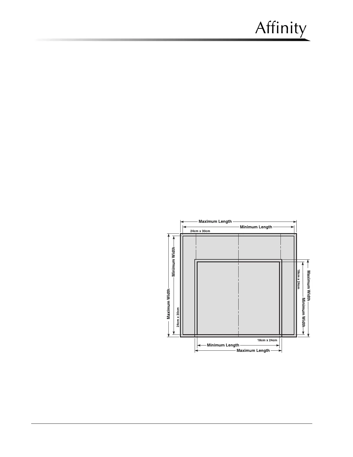
7.1 X-ray Beam Alignment Template
The translucent X-ray Beam Alignment Template (LORAD P/N 3-405-8010), shown in Figure
4-10 must be positioned on the unit’s image receptor support on top of a 14 x 17 cm cassette
screen (Lanex Med). The visible borders of the x-ray field can be compared with graduations
on the template to determine coarse x-ray field alignment
The template contains minimum and maximum borders for the left, right, and rear field
edges of the 18 x 24 cm format and the 24 x 30 cm format. For the chest wall edge, a
maximum limit (6.5 mm) is provided to adjust for chest wall edge overlap.
Always position the X-ray Beam
Alignment Template accurately
on the image receptor support
by performing the following:.
1. Place the screen (facing up)
onto the support device and
center it.
2. Move the screen forward
(away from the C-arm)
approximately 1.5". Lay the
template on top of the
screen.
3. Butt the rear edge of the
template against the C-arm
to place the image receptor
tray edge line directly
above the edge of the
image receptor support
device.
4. Center the template left-to-
right until the cut in edges
(at the rear of the template)
are set flush with the sides of the image receptor support.
Figure 4-10: X-ray Beam Alignment Template