P/N 9-500-0255 4-49
Service Manual
Chapter 4: Calibrations and Performance Checks
X-ray and Light Field Check and Alignment Procedures
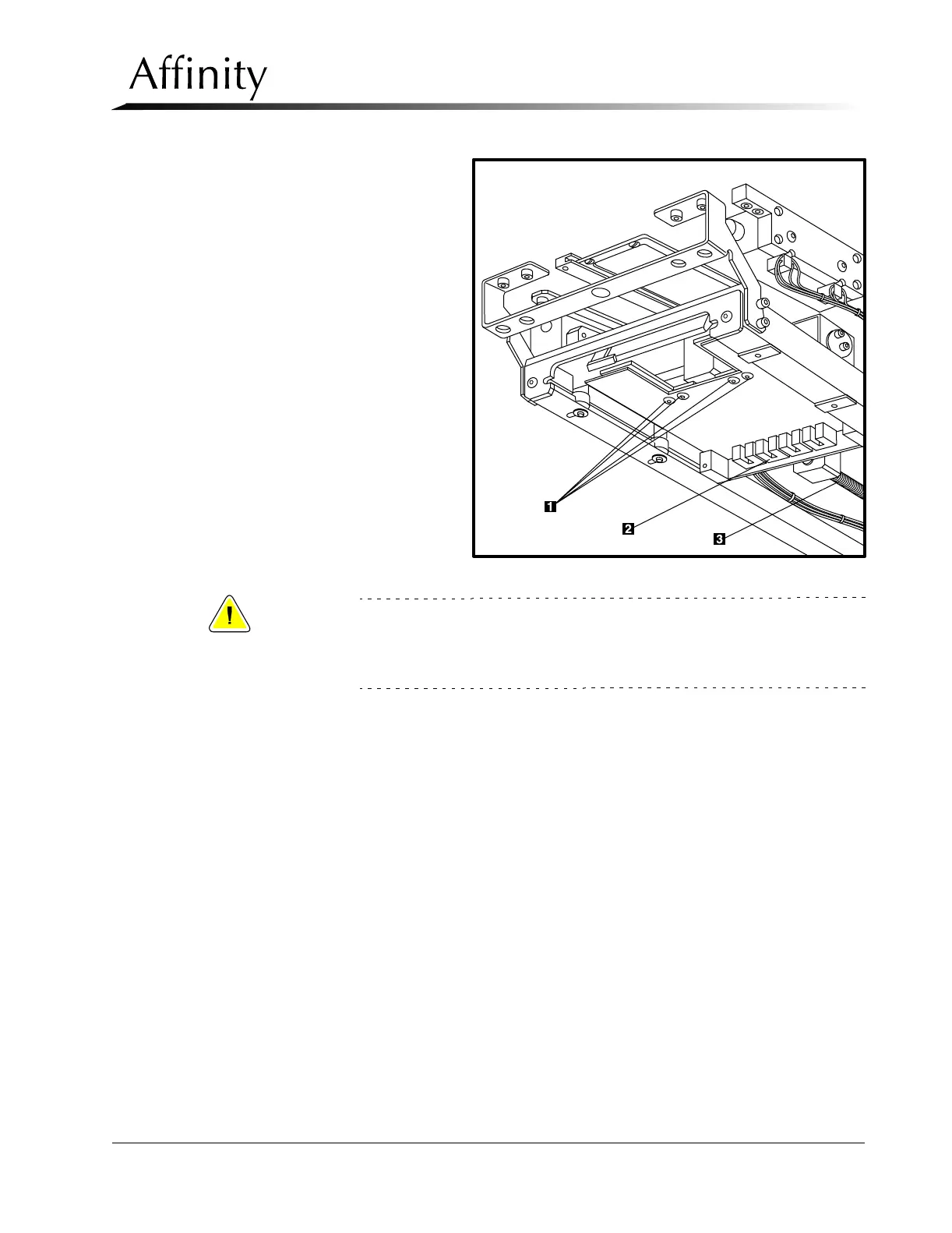
Legend for Figure 4-13
1. Auto Aperture Adjustment
Blades Screws (4)
2. Aperture Sensor
3. Worm Gear—Auto Aperture
Motor Axis
Figure 4-13: Auto Aperture Alignment—18 x 24 cm Large Focal Spot
Caution:
Never backdrive any axis (manually turning worm gear (Figure 4-13, Item
3) on the auto aperture motor) because it will destroy the gearhead.
Always use the motor control (SW1 on Tubehead Control Board) to move
around each axis.
C. If the back edge field adjustment is off, reposition by relocating the auto
aperture sensor to match the new location of the rear edge of the aperture.
Cycle the IN/OUT position of the auto aperture by using SW1 on the Tube-
head Control Board, take exposures and verify position.
D. Making exposures as necessary, adjust the right blade to align within the
markings on the alignment template. Tighten the two screws securing the
blade.
E. Making exposures as necessary, adjust the left blade to align within the
markings on the alignment template. Tighten all screws (including the sen-
sor screw).