B-6 P/N 9-500-0255
Service Manual
Appendix B: Technical References
LED Indicators
3.0 LED Indicators
Use the following LED Indicator tables as an aid for troubleshooting the Affinity.
• Table B-12 - Tubehead Control Board (PN 1-003-0403).
• Table B-13 - Display Microprocessor Board (PN 1-003-0428).
• Table B-14 - C-arm Safety Board (PN 1-003-0440).
• Table B-15 - Relay Protection Board (PN 1-003-0490)
• Table B-16 - Host Microprocessor Board (PN 1-003-0493) LED Indicators
• Table B-17 - Host Microprocessor Board—C-arm Switch Multiple Function Indications
• Table B-18 - HV Control Filament Board (PN 1-003-0485) LED Indicators
Table B-12: Tubehead Control Board (1-003-0403) LED Indicators
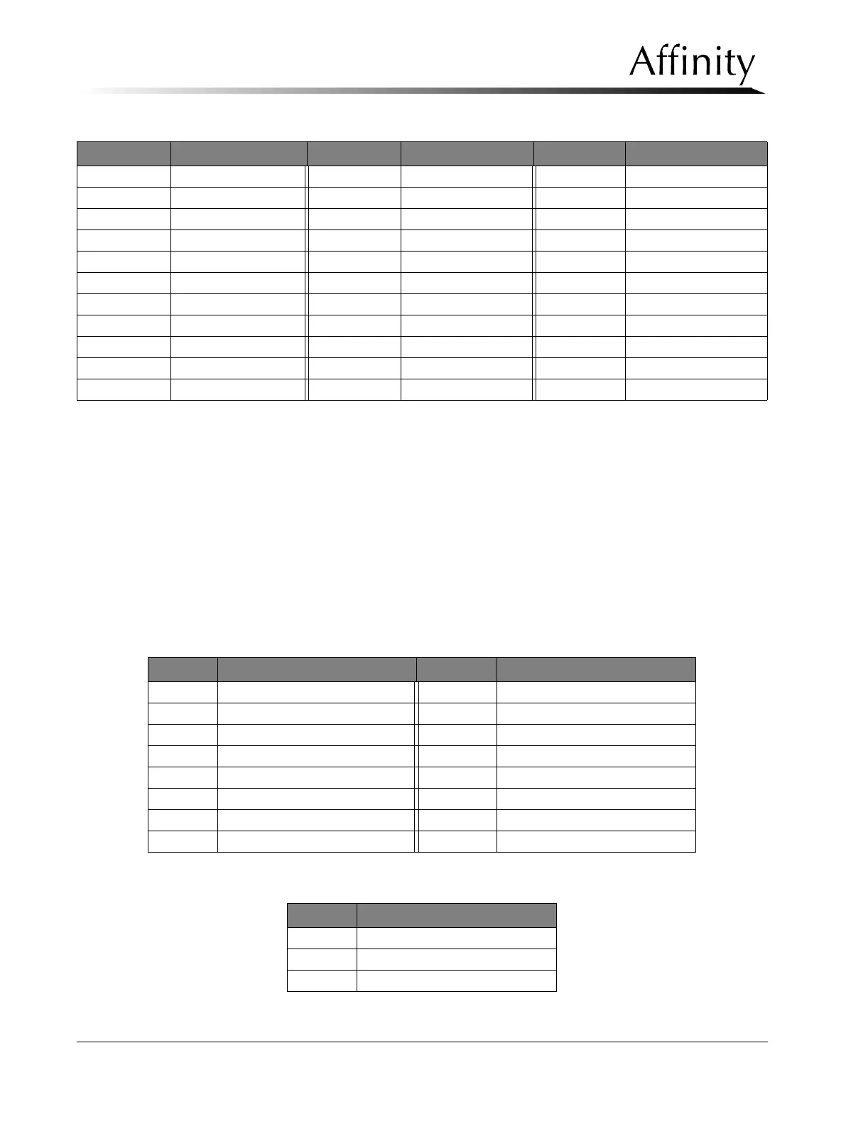
Table B-13: Display Microprocessor Board (PN 1-003-0428) LED Indicators
TP15 Rotor OC ADJ TP40 HV Enable TP65 +22U
TP16 Filament Fault TP41 GND TP66 P+ 14 V
TP17 INV OC ADJ TP42 kV Control TP67 HV COM
TP18 HDGND TP43 Brake Relay TP68 -15 V
TP19 Over Current SET TP44 Brake Time TP69 Filament Return
TP20 Rotor IP TP45 Brake TP70 GND
TP21 ICOM Sense TP46 HV Fault TP71 LG OC SET
TP22 Filament Shut Down TP47 Boost Time TP72 SM OC SET
TP23 +2.5 V TP48 -VP Local TP73 LG GR SET
TP24 +22U RTN TP49 Over Voltage Fault TP74 SM GR SET
TP25 Over Voltage TP50 VC
LED LED “ON” Indication LED LED “ON” Indication
D1 Green = Run D9 Mirror Out
D2 Aperture 2 ID D10 Lamp Large
D3 Aperture 1 ID D11 Lamp Out
D4 Aperture 4 ID D12 Aperture IN
D5 Aperture 3 ID D13 Aperture OUT
D6 Green = Motor Fault D14 Filter Rhodium
D7 Red = Motor Over Current D15 Filter Molybdenum
D8 Mirror Large
LED LED “ON” Indication
D3 Software Activity
D4 Software Activity
D5 Software Activity
Test Point Voltage/Signal Test Point Voltage/Signal Test Point Voltage/Signal