4-2 P/N 9-500-0255
Service Manual
Chapter 4: Calibrations and Performance Checks
Calibration Procedures
2.1 Entering Calibration Mode
The Affinity Series has four calibration screens which are used to setup and calibrate the x-
ray generating system, the automatic exposure control system, and the electro-mechanical
sub-systems (compression force, thickness, etc.).
Perform the following to access the Calibration Mode screens:
1. Turn the unit off.
2. To access the Host Microprocessor Board (Figure 6-1, Item 7), remove the Gantry right-
side panel as per Chapter 6, Section 2.1.1.
3. Locate DIP switch (S2) at the lower right side of the Microprocessor Board. Set the unit
for the Service Mode (S2 switch 1 = ON). Table 4-1 shows all the switch settings and
their functions.
4. Turn power ON. When the Run Mode appears, the unit is in the Service Mode.
5. The three user screens (Run Mode, User Default, and Exposure Default), the Debug
screen, and the three calibration screens (Cal #1, Cal #2, Cal #3, and Cal #4) are now
accessible by pressing Reset + Left Arrow or Reset + Right Arrow.
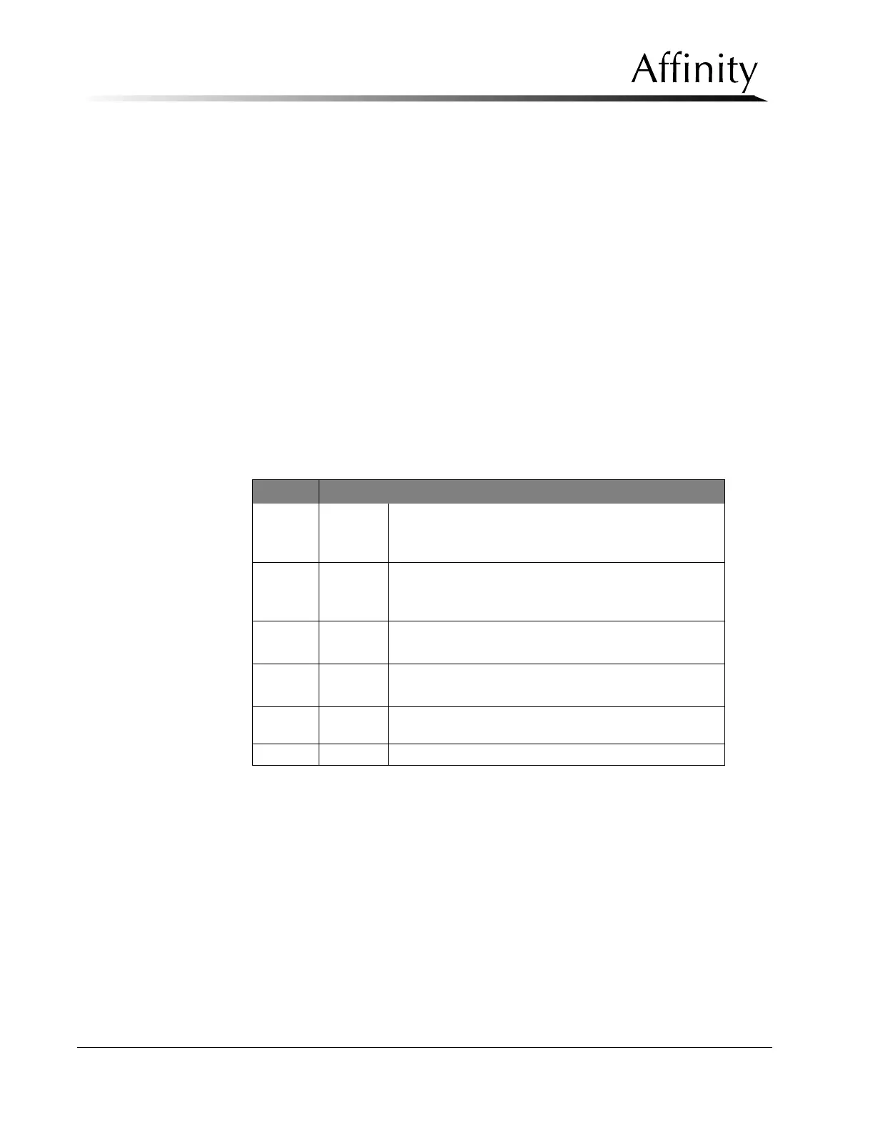
Table 4-1: Microprocessor S2 DIP Switches
Switch Function (0=OFF/1=ON)
1ON
—Service Mode/post exposure standby, 30, 45, or 60 sec
selectable in Cal Screen #4
OFF —User Mode/20 sec standby
2ON
—Disables CF and tubehead communication when not
part of system
OFF —Normal Operations
3ON—Disables X-ray Footswitch
OFF —Enables X-ray Footswitch (Normal Operations)
4ON—Enables display of actual mAs in manual mode.
OFF —Normal Operations
5
ON
OFF
—Enables Adaptive Filament Function
—Disables Adaptive Filament Function
6-8 --- Reserved for language (future use)