P/N 9-500-0255 4-33
Service Manual
Chapter 4: Calibrations and Performance Checks
Performance Checks
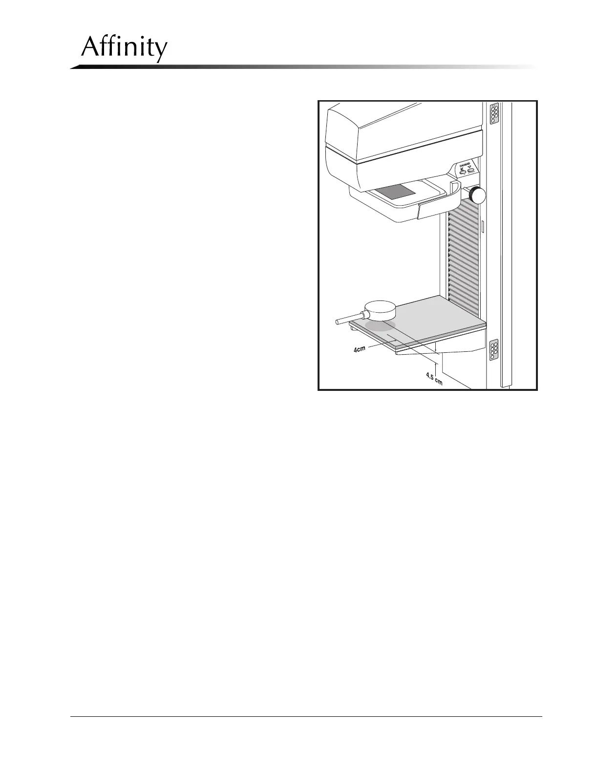
1. Place a radiation probe 4.5 cm
above the image receptor sup-
port device. Position the probe
4.0 cm from the chest wall
edge, and center it laterally with
respect to the left and right
edges of the IRSD (Figure 4-6).
Set the meter functions switch
to milliroentgens.
2. Install the 18 x 24 cm compres-
sion paddle upside-down on the
compression device. Raise the
compression device completely.
Ensure the probe’s meter is posi-
tioned so that it can be read
from behind the unit’s radiation
shield.
3. In the RUN MODE, set the unit
for a Manual Mode exposure at
30 kV, 70 mAs, Large focal spot,
Mo filter.
4. Insert the Auto-aperture into the
tubehead slot, conduct the
exposure, and record the mil-
liroentgen reading on the semi-
log (Table 4-13).
5. Place a 0.2 mm aluminum filter
(99.9% pure aluminum) on the surface of the compression paddle, directly beneath the
x-ray tube port (Figure 4-6). Using the same technique factors as in Step 3, make another
exposure and record the milliroentgen reading on the semi-log.
6. Repeat Step 5 with additional 0.1 mm sheets of aluminum between the x-ray tube port
and the radiation probe. Record the milliroentgen reading on the semi-log after each
exposure until the reading is less than one-half the original step #4 exposure reading
(without aluminum).
7. Draw a line on the semi-log through the plotted mR readings. It may be necessary to
draw the line to achieve a “best fit” path (in cases where the plotted readings are not lin-
ear).
8. Determine the exact half-value of the step #4 mR reading and record this on the semi-
log. Draw a horizontal line, starting from this plot, across the semi-log until it intersects
with the line plotted in Step 7.
9. Draw a vertical line through the intersection to the bottom of the semi-log. This is the
half-value layer. Verify that the half-value layer is greater than 0.33 mm AL, and less than
0.42 mm AL (Molybdenum filter).
10. Select the Rhodium (Rh) filter, then repeat Steps 4 through 9 to obtain the half-value
layer for the Rhodium filter. Verify that the half-value layer is greater 0.33 mm AL, and
less than 0.49 mm AL (Rhodium filter).
Figure 4-6: Half-Value Layer Setup