6-54 P/N 9-500-0255
Service Manual
Chapter 6: Maintenance—Remove and Replace Procedures
C-Arm Components—Remove and Replace
10. Loosen the clamp screw (1) on the end of the potentiometer (2) shaft. Remove
the clamp and the sprocket (3) together.
11. Remove the hex nut (4) that secures the potentiometer to the mounting bracket
(5). Slide the potentiometer off the bracket.
12. To replace the compression display potentiometer, reverse Steps 8 through 11
above. Do not tighten clamp screw at this time.
13. Perform the Compression Display Potentiometer Adjustment as per Chapter 4,
Section 8.2.
14. Replace the IRSD covers, the tubehead covers, the compression device
assembly upper and lower covers, the C-arm bottom cover and left side cover.
15. Replace the compression accessory. Restore power to unit.
3.4 IRSD Components
This section details the removal and replacement procedures for the components inside the
image receptor support device (IRSD). The alignment, adjustment and/or calibration
procedures are provided as required.
3.4.1 Image Receptor Support Device Covers
To access the AEC
board, the AEC
detector board,
image receptor
detector board, and
the AEC Position
Compression Display
Microprocessor,
remove the IRSD
covers as follows
(refer to Figure 6-38
throughout the
following):
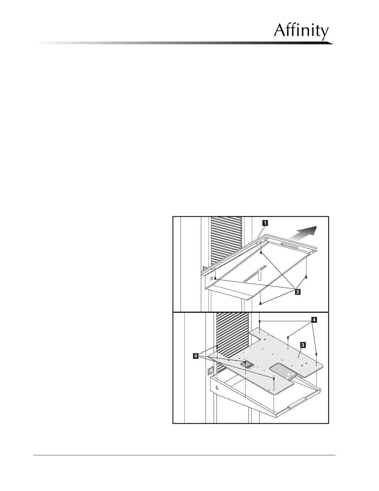
1. Turn power OFF,
then unplug the
power recepta-
cle from the wall
outlet.
2. Loosen and
remove the 4
screws (Item 2)
that secure the
black anodized
top cover (Item
1) to the
aluminum top
plate (Item 3).
Figure 6-38: IRSD Covers—Removal