B-4 P/N 9-500-0255
Service Manual
Appendix B: Technical References
Test Points
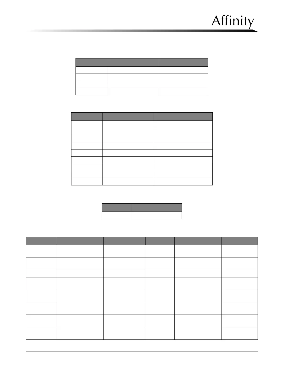
Table B-7: AEC Position Compression Display (PN 1-003-0472) Test Points
Table B-8: Auxiliary Power Distribution Board (PN 1-003-0489) Test Points
Table B-9: Communications Interface Board (PN 1-003-0434) Test Points
Table B-10: Host Microprocessor Board (PN 1-003-0493)
Test Point Voltage/Signal Function
TP1 +2.5 V +2.5 V
TP2 FORCE +0.25 V to +1.5 V
TP3 THICKNESS +0.05 V to +2 V
TP4 GND ---
Test Point Voltage/Signal Function
TP1 +15 V Tubehead Motor
TP2 +24 V Bucky Power (Regulated)
TP3 -15 V StereoLoc II
TP4 +15 V StereoLoc II
TP5 +22 V Filament Power
TP6 DGND ---
TP7 -25 V Tube Control
TP8 +25 V Tube Control
TP9 +35 V Bucky Power (Unregulated)
Test Point Voltage/Signal
TP1 GND
Test Point Voltage/Signal Function Test Point Voltage/Signal Function
TP1 kV Control 0 V to +10 V TP27 C-Arm Angle Display
Slave Select
Clock
TP2 KV Sense 0 V to +10 V TP28 C-Arm Angle Display
Serial
Clock
TP3 mA Sense 0 V to +10 V TP29 MOSI2 Clock
TP4 HV Fault Passive = +5 V
Active = 0 V
TP30 Grid in Motion Clock
TP5 Rotor Okay Active = +5 V
Passive=0V
TP31 Detent Active = +5 V
TP6 HV Enable/Backup
Timer
Active = +5 V
Passive=0V
TP32 +5 V ---
TP7 HV Reset Active = +5 V
Passive=0V
TP33 AEC 0Vto+10V
TP8 N/A --- TP34 Bucky Cassette Active = +5 V
Passive=0V