4-42 P/N 9-500-0255
Service Manual
Chapter 4: Calibrations and Performance Checks
Performance Checks
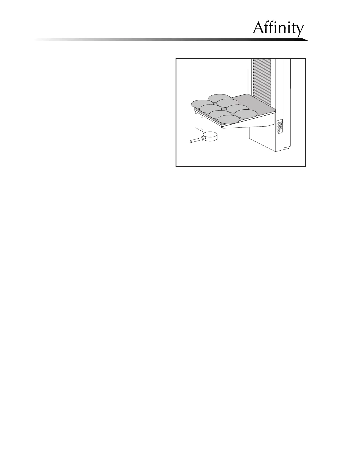
2. Place a 1/16 inch thick (1.6
mm) sheet of lead with a 5 inch
(12.7 cm) diameter hole in it on
the IRSD. Slide this lead sheet
to position the hole at the posi-
tion marked “A” (Figure 4-8).
Collimate the x-ray field to the
18 x 24 cm field size.
3. Position the probe beneath the
image receptor support relative
to the center of the hole in the
lead sheet. Raise or lower the
support stand until the probe is
exactly 5 cm below the bottom
of the IRSD. Face the probe’s
detector surface toward the x-
ray source.
4. Apply power, then set the unit
for a Manual mode exposure at
39 kV, 220 mAs, Large focal spot. Conduct the exposure and record the mR reading. If
the reading is greater than 0.10 mR, contact L
ORAD Technical Support.
5. Repeat this entire procedure for positions “B,” “C,” and “D” in Figure 4-8.
6. Install the 24 x 30 cm Bucky (if used). Repeat this test for positions “E”, “F”, “G” and “H”
(Figure 4-8) for the 24 x 30 cm Bucky.
7. If there are any readings greater than 0.10 mR, contact L
ORAD Technical Support.
6.11 X-ray Tubehead Leakage Check
This check is performed at the factory and is not required at installation. However, it will be
necessary to perform this check after repair or replacement of the tubehead housing or the
lower tubehead cover.
1. Connect a radiation scatter probe (100 square cm) to the readout/logic module of a radi-
ation rate meter.
2. Set the meter’s operating mode to read in milliroentgens per hour (mR/Hour). Place the
readout/logic module so that it can be viewed from behind the radiation shield
Figure 4-8: IRSD Shielding Check
C
G
E
A
SCATTER
PROBE
5 cm
B
F
D
H