B-8 P/N 9-500-0255
Service Manual
Appendix B: Technical References
Image Receptor Detect Board—Sensor Combinations
Table B-18: HV Control Filament Board (PN 1-003-0485) LED Indicators
4.0 Image Receptor Detect Board—Sensor Combinations
A strip of tape, on the bottom of each image receptor, blocks the 4 optical sensors on the Accessory Detect Board
(refer to Figure 6-18 for component location and identification). The strip is patterned using reflective and non-
reflective material. Blocking an optical sensor with the reflective material causes that sensor to generate a logic
high signal; blocking it with the non-reflective material causes the sensor to remain at a low logic.
The combination of these highs and lows generate the signals which are used to determine the installed image
receptor holder.
Use Table B-19 to verify the optical sensor combinations for each image receptor. Note that “H” signifies a logic
high (reflective: 3.5 - 5.0 VDC), while “L” signifies a logic low (non-reflective: 0.5 - 1.5 VDC). Note that the fifth
column in Table B-19 provides a graphic representation of the HEX code strip found on each image receptor. The
light boxes represent a logic high (reflective) while the dark boxes represent a logic low (non-reflective). The
number code given is the code which appears on the Debug Screen for the individual image receptors (when
installed).
LED Color LED “ON” Indication LED Color LED “ON” Indication
D4 RED GRID D40 GRN R+ 14 V
D29 RED HV Interlock D41 GRN HV Enable
D30 RED INV Interlock D43 RED Rotor Over Current
D32 RED ARC D57 RED Tube Over Current
D33 RED INV Over Current D67 GRN Filament Enable
D35 RED Tube Over Voltage D68 GRN SM Focal Spot
D37 GRN -15 V D70 GRN LG Focal Spot
D38 GRN +5 V D71 RED Over Current
D39 GRN +15 V D75 RED Over Voltage
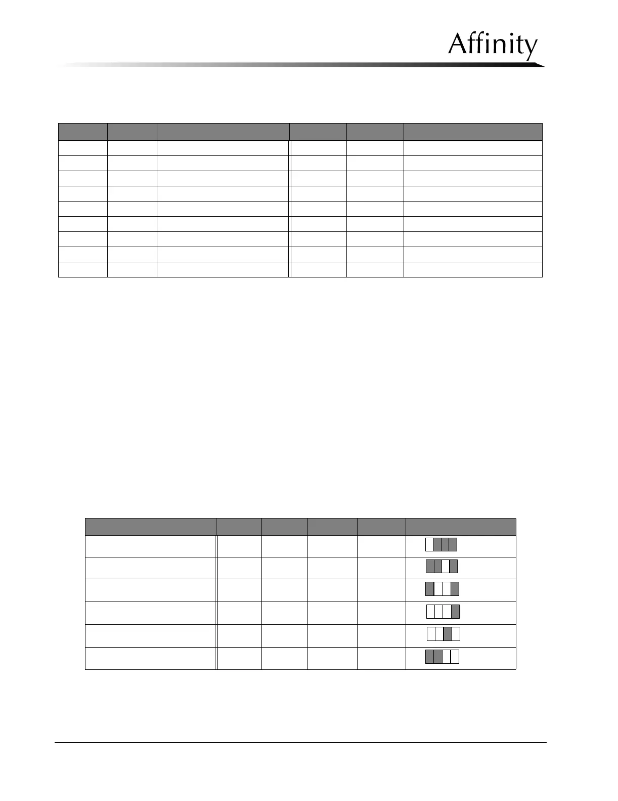
Table B-19: Image Receptor Sensor Combinations
Image Receptor ISO4 ISO3 ISO2 ISO1 Hex Code
Mag Table H L L L
8=
18 x 24 cm Cassette Holder L H L L
4=
18 x 24 cm HTC Bucky L H H L
6=
24 x 30 cm HTC Bucky H H H L
E=
18 x 24 cm SRL 2000 Bucky H H L H
D=
24 x 30 cm SRL 2000 Bucky L L H H
3=