6-38 P/N 9-500-0255
Service Manual
Chapter 6: Maintenance—Remove and Replace Procedures
C-Arm Components—Remove and Replace
3.2.3 Tubehead Control Board
1. Remove power from the unit. Remove the aperture (if installed) from the slot in
the tubehead, then remove the tubehead covers as per Section 3.2.1.
Note… If it is only necessary to replace the firmware chip (U9), skip to Step 6 now.
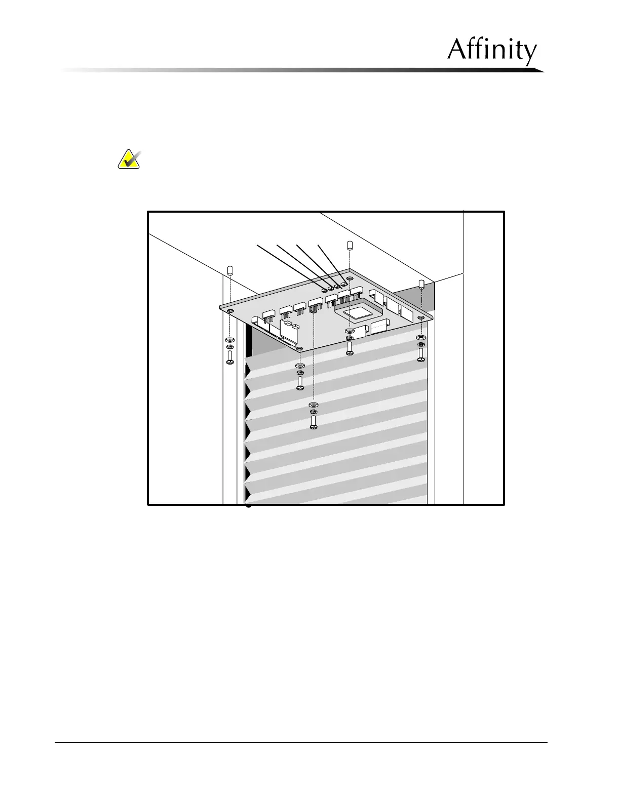
2. Disconnect the wiring harness connectors on the Tubehead Control Board
(Figure 6-26). Note locations.
Figure 6-26: Tubehead Control Board—Removal
3. Remove the five screws that secure the Tubehead Control Board to the standoffs
on the tubehead chassis.
4. Pull the board out of the unit.
5. Reverse procedures to replace the board. Skip to Step 7.
6. Replace the Firmware Chip (U9) as per Section 2.5.2, Firmware Replacement,
then go to Step 7.
7. Verify the board operation as follows (refer to Table 6-1and Figure 6-26):
A. Turn power ON to unit.
B. Press S1 once on Tubehead Control Board, verify the auto aperture moves
out of the field.
C. Press S1 a second time, verify the auto aperture moves back in.
S1 S2 S3 S4