4-56 P/N 9-500-0255
Service Manual
Chapter 4: Calibrations and Performance Checks
Mechanical Adjustments
8.0 Mechanical Adjustments
The following mechanical adjustments may be required after servicing the compression
system.
8.1 Compression Chain Tension Adjustment
Perform this procedure after servicing or replacing the Compression Motor and Brake
Assembly or the Compression Clutch and Brake Assembly.
1. Rotate C-arm to +45°.
2. Turn the unit OFF.
3. Remove the Gantry’s right side panel (to access the Host Microprocessor board) as per
Chapter 6, Section 2.1.1.
4. On the Host Microprocessor board, set the unit for the service mode (S2 switch 1 = ON).
5. Remove the lower compression device cover as per Chapter 6, Section 3.3.1.
6. Remove the C-arm upper rear cover, and the C-arm top cover as per Chapter 6, Section
3.1.2.
7. Move the compression device
up completely.
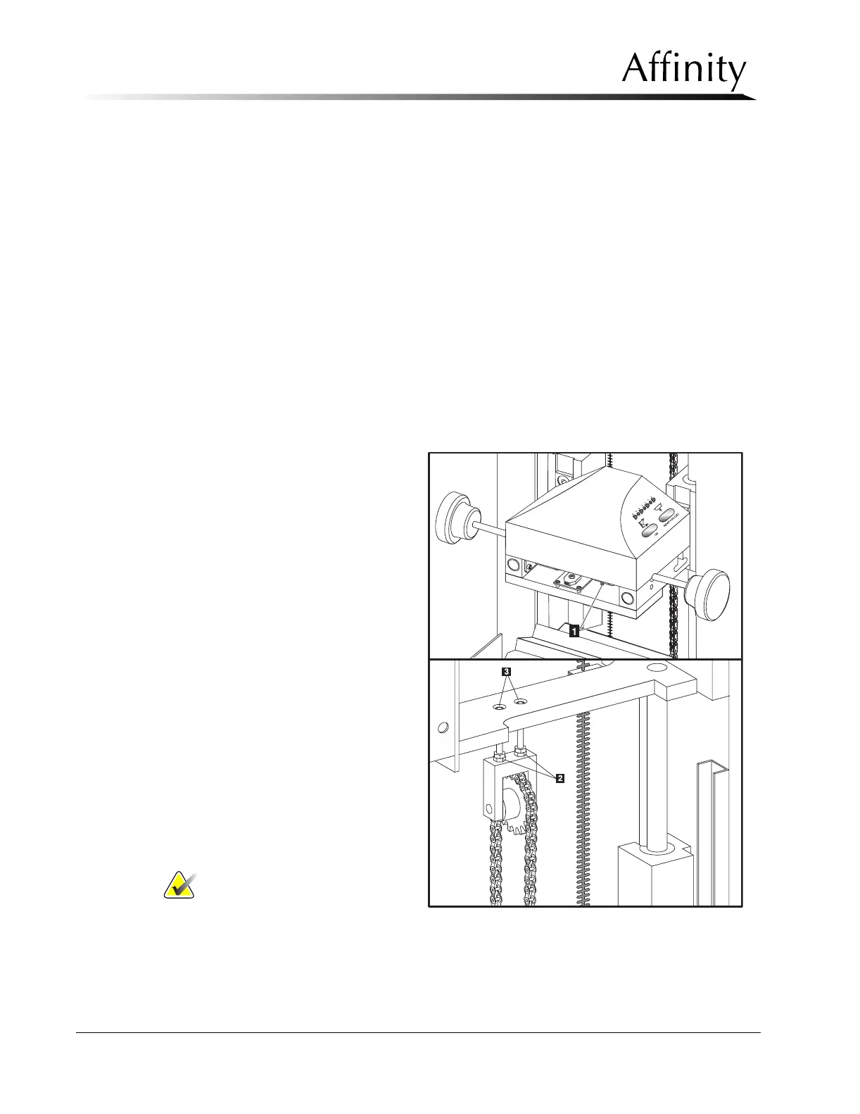
8. Loosen the Dog Point Set
Screw (Figure 4-18, Item 1).
The set screw is loosened from
the bottom of the compression
device.
9. Loosen the two lock nuts (Fig-
ure 4-18, Item 2) of the chain
tension assembly, then evenly
turn the adjustment screws
(Figure 4-18, Item 3) to raise or
lower the tension sprocket.
10. Tighten the dog point set screw
and check the chain tension.
From behind the C-arm push
on the compression chain
between the upper and lower
sprockets. Check for compres-
sion chain deflection (total
throw) between 1/4" and 1/2".
11. Turn the unit ON.
12. Rotate C-arm to 0°.
Note… Do not overly
force the chain to
achieve the
desired deflection.
Chain movement should be effortless.
Figure 4-18: Adjustment - Compression Motor Chain