P/N 9-500-0255 6-41
Service Manual
Chapter 6: Maintenance—Remove and Replace Procedures
C-Arm Components—Remove and Replace
3.2.5 Beam Limiting Assembly
The Beam Limiting Assembly consists of the following components:
• Aperture Detect Board
• Dual Filter Assembly (with Filter Position Detectors)
• Light Field Lamp Assembly with Fan
• Motorized Mirror Assembly
3.2.6 Aperture Detect Board
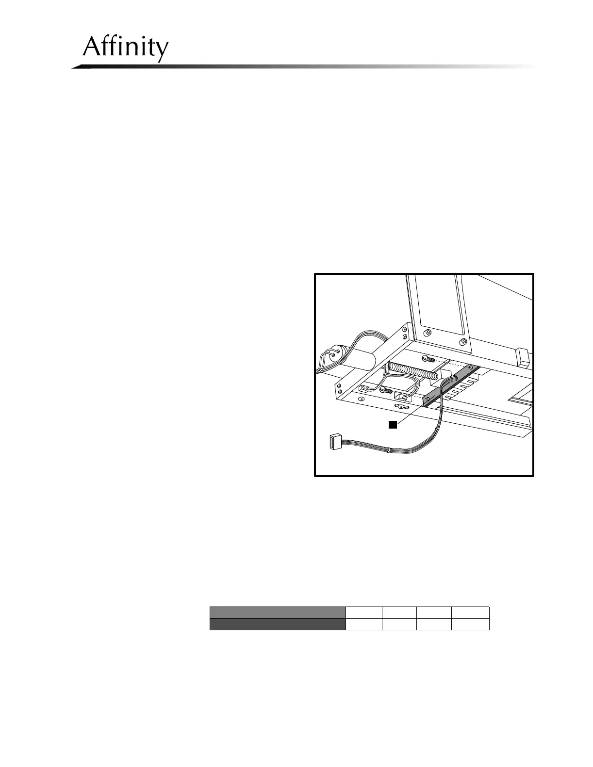
The Aperture Detect board (Figure 6-28, Item 1) is mounted on the beam limiting
device at the rear of the aperture slot. This board contains four optical sensors that
detect
• the presence of an aperture and
• the type of aperture installed.
1. Remove the lower
tubehead covers as per
Section 3.2.1.
2. Disconnect the wiring
harness from the
Tubehead Control
Board (Figure 6-26).
Note location.
3. Remove the 2
mounting screws that
secure the board to the
tubehead chassis. Pull
the board out of the
unit.
4. Reverse this procedure
to install the
replacement Aperture
Detect Board. Do not
replace the tubehead
covers at this time.
5. Verify that the optical sensors on the board are working properly as follows:
A. Block each sensor with a piece of dark color paper. The left most sensor is
sensor #1; the right most sensor is sensor #4.
B. A corresponding LED on the Tubehead Control Board will light when each
sensor is blocked, then go out when unblocked (see the matrix below).
6. Replace the tubehead covers.
Optical Sensor 1234
Tubehead Control Board LED D3 D2 D5 D4
Figure 6-28: Aperture Detect Board—Removal
1