P/N 9-500-0255 2-5
Service Manual
Chapter 2: System Installation
Unit Installation
After determining the input voltage range, verify the unit’s isolation transformer is correctly
set (re-configure as required).
The following explains how to access the input power assembly chassis and re-configure the
isolation transformer taps to match the source voltage measured previously.
1. Flip the circuit breaker on the rear of the Gantry down (OFF).
2. Remove the Gantry Upper Rear panel as per Chapter 6, Section 2.1.2. Set the cover
aside.
3. Remove the Rear Connector panel and shroud as per Chapter 6, Section 2.1.3. Pull the
panel slightly away from the unit, then let it hang by the attached wiring harness.
4. To gain access to the input power assembly chassis, remove the Lower Rear panel as per
Chapter 6, Section 2.1.4, Steps 1 through 3. The isolation transformer is mounted on the
lower shelf of the input power assembly chassis.
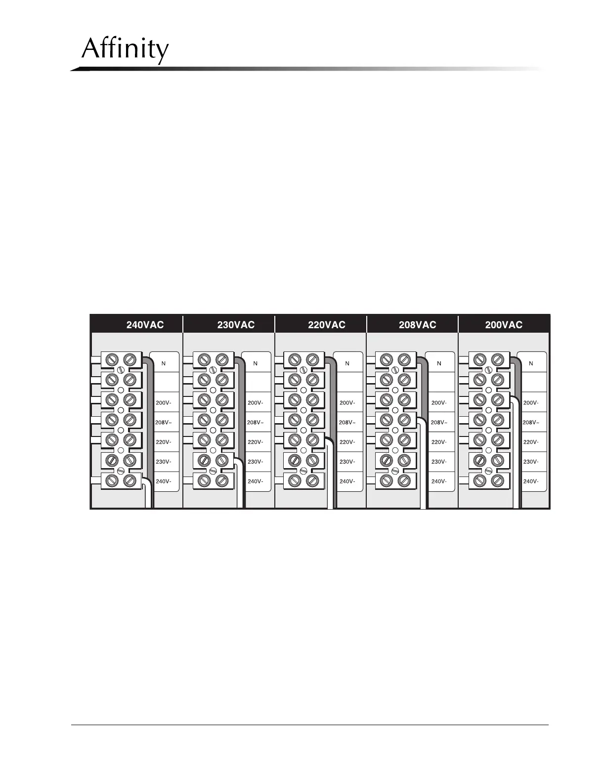
5. Configure the input wiring to tap the transformer so that it matches the previously mea-
sured source voltage (refer to Figure 2-3).
Figure 2-3: Isolation Transformer Taps
3.2 Power Cable Connection
The power cord will need to be hardwired into the power source. This should be done by a
certified electrician.