P/N 9-500-0255 B-7
Service Manual
Appendix B: Technical References
LED Indicators
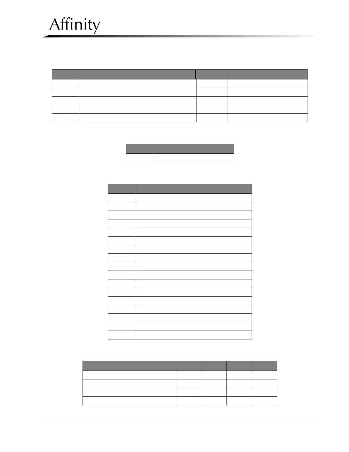
Table B-14: C-arm Safety Board (PN 1-003-0440) LED Indicators
Table B-15: Relay Protection Board (PN 1-003-0490) LED Indicators
Table B-16: Host Microprocessor Board (PN 1-003-0493) LED Indicators
Table B-17: Host Microprocessor Board—C-arm Switch Multiple Function Indicators
LED LED “ON” Indication LED LED “ON” Indication
D1 +5 V D6 ACC0
D2 Actuator Fault D7 ACC1
D3 Load Cell Fault (load cell at limit) D8 ACC2
D4 Clock signal (flickers to indicate board is working) D9 VCC
D5 CAL Mode Initiated D10 -5 V
LED LED “ON” Indication
D1 No power to Board
LED LED “ON” Indication
D1 +5 V
D2 +12 V
D3 -12 V
D4 LED Serial CLK (Flickers when operating)
D5 C Angle (Flickers when operating)
D6 MOSI (Flickers when operating)
D7 COMP MISO (Flickers when operating)
D8 COMP SS (Flickers when operating)
D9 TUBE SS (Flickers when operating)
D15 Unit set to Large Focal Spot
D16 Unit in Boost mode
D17 Unit in BRAKE mode
D18 Unit in RUN mode
D19 Filament Enabled
D25 Rotation Brake Released
D26 Actuator Down
D27 Actuator Up
C-Arm Switch Function D21 D22 D23 D24
Compression Release Active when: ON ON OFF OFF
CompressionDownActivewhen: OFF ON OFF ON
Compression Up Active when ON ON OFF OFF
Compression Brake Engaged when OFF OFF ON ON