6-22 P/N 9-500-0255
Service Manual
Chapter 6: Maintenance—Remove and Replace Procedures
Gantry Components—Remove and Replace
2.6.3 The C-arm Rotation Potentiometer
The C-arm rotation assembly is made up of a 10-turn, 500 ohm potentiometer with a
14-tooth gear and a timing belt.
1. Remove power, then remove the upper rear Gantry panel as per Section 2.1.2.
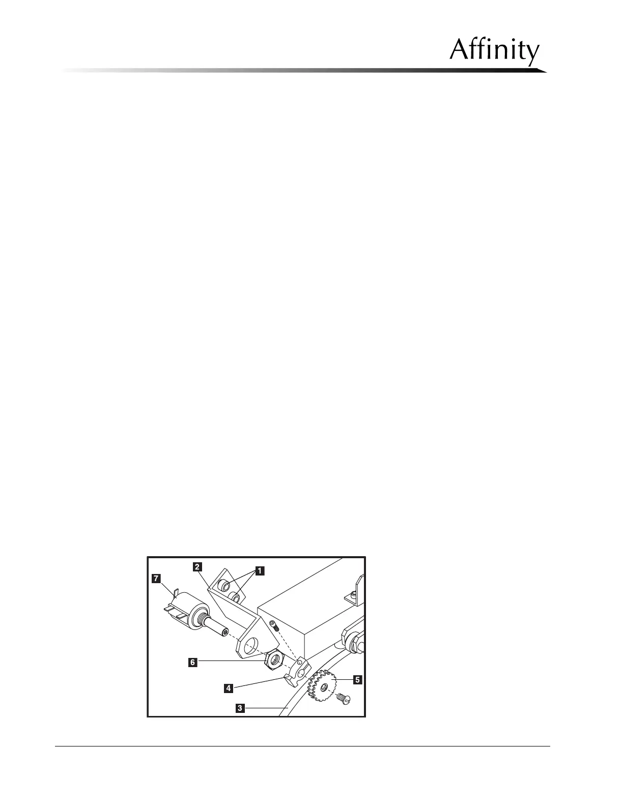
2. Remove the 2 screws (Figure 6-12, Item 1) that secure the potentiometer bracket
(Figure 6-12, Item 2) to the VTA. Carefully slip the sprocket off the timing belt
(Figure 6-12, Item 3).
3. Note the post locations of the 3 wires on the potentiometer (Figure 6-12, Item
7), then cut them as close to the terminals as possible.
4. Pull the potentiometer with attached bracket out of the Gantry. Loosen the
clamp screw on the potentiometer shaft, then pull the clamp (Figure 6-12, Item
4) and sprocket (Figure 6-12, Item 5) off together.
5. Remove the hex nut (Figure 6-12, Item 6) and internal tooth lock washer that
secures the potentiometer to the mounting bracket. Pull the potentiometer out of
the mounting bracket.
6. Secure the replacement potentiometer onto the mounting bracket using the
previously removed lock washer and hex nut.
7. Install the clamp and sprocket previously removed onto the potentiometer shaft.
8. Strip and tin the tips of the three wires previously cut, then solder them to their
respective posts on the potentiometer.
9. Loosely secure the potentiometer bracket on the VTA using the previously
removed hardware. Turn the pot fully clockwise, then back off 1/4-turn
counterclockwise.
10. Apply power, then rotate the C-arm completely counterclockwise (-150°).
Carefully slip the belt onto the sprocket. Be sure that the teeth on the belt seat
firmly into the gears of the sprocket.
11. Tighten the belt by adjusting the position of the potentiometer bracket on the
VTA, then tighten the mounting screws. The tension is adjusted properly when
the belt deflection is approximately 1/4" using moderate pressure.
12. Rotate the C-arm through the entire range of rotation and verify that the angle
display is accurate. When complete, replace all previously-removed covers.
Figure 6-12: C-arm Rotation Potentiometer—Removal