P/N 9-500-0255 6-33
Service Manual
Chapter 6: Maintenance—Remove and Replace Procedures
C-Arm Components—Remove and Replace
3.1.4 3-Position Switch Board
The 3-Position C-arm Switch Board is a triple switch membrane-type pad used to
control C-arm Up, C-arm Down, and C-arm Rotation Release. The switch pad has
an adhesive which secures it to the C-arm Top Cover.
1. Remove power from the unit. Remove the C-arm Top Cover as per Section
3.1.2.
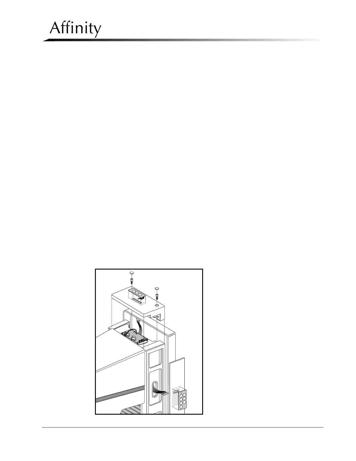
2. Disconnect the wire harness from 3-position C-arm Switch Pad on Top Cover.
3. Peel the 3-Position switch pad off of the Top Cover. See Figure 6-22. Pull the
ribbon cable and connector through the slot in the top cover to remove.
4. Reverse this procedure to install the replacement 3-Position Switch Pad.
5. Apply Power, then perform the Tubehead Controls Functional Checks as per
Chapter 3, Table 3-1, “Post Power-Up Checks”.
3.1.5 7-Position Switch Board
The C-arm houses four 7-Position C-arm Switch Boards, two on each side of the C-
arm. The boards, which are membrane-type switch pads, mount to the C-arm Side
Covers using an adhesive backing.
1. Remove power from the unit. Remove the C-arm Bottom Cover as per Section
3.1.2.
2. Remove the appropriate C-arm Side Cover (left or right) as per Section 3.1.2.
Disconnect the wiring harness from the upper and lower switch pad connectors.
3. Peel the 7-Position switch pad in question off of the Side Cover. See Figure 6-22.
Pull the ribbon cable and connector through slot in side cover to remove.
4. Reverse this procedure to install the replacement 7-Position Switch Pad.
5. Apply Power, then perform the C-arm Controls Functional Checks as per
Chapter 3, Table 3-1, “Post Power-Up Checks”.
Figure 6-22: C-arm Switch Pads—Removal