P/N 9-500-0255 2-9
Service Manual
Chapter 2: System Installation
Unit Installation
1. Secure the exposure footswitch mounting bracket to the Gantry base plate using
two screws (supplied) on the right side of the Gantry.
Note… When the Gantry right side cover is installed, the exposure footswitch will
be positioned below the Control Panel).
2. Connect the exposure footswitch cable to the x-ray connector (Figure 2-6, Item
5).
A. Align the key in the footswitch connector to the keyhole in the receptacle.
A. Push the connector straight in until it stops.
3. Locate DIP switch (S2) at the lower right side of the Host Microprocessor board
(Gantry right-side panel removed). Enable the X-ray Footswitch by setting S2
switch 3 to OFF.
3.6.2 Dual Function Footswitch(es)
A dual-function footswitch provides C-arm and Compression Up or Down
movement. Normal system configuration consists of one footswitch with an optional
second footswitch. Two jacks (on the lower rear of the Gantry) provide connections
for the Footswitch(es). To connect the Footswitch(es), perform the following:
1. Connect the Footswitch(es) connector to the left and/or right Footswitch recepta-
cles (Figure 2-6, Item 6) on the Gantry connection panel.
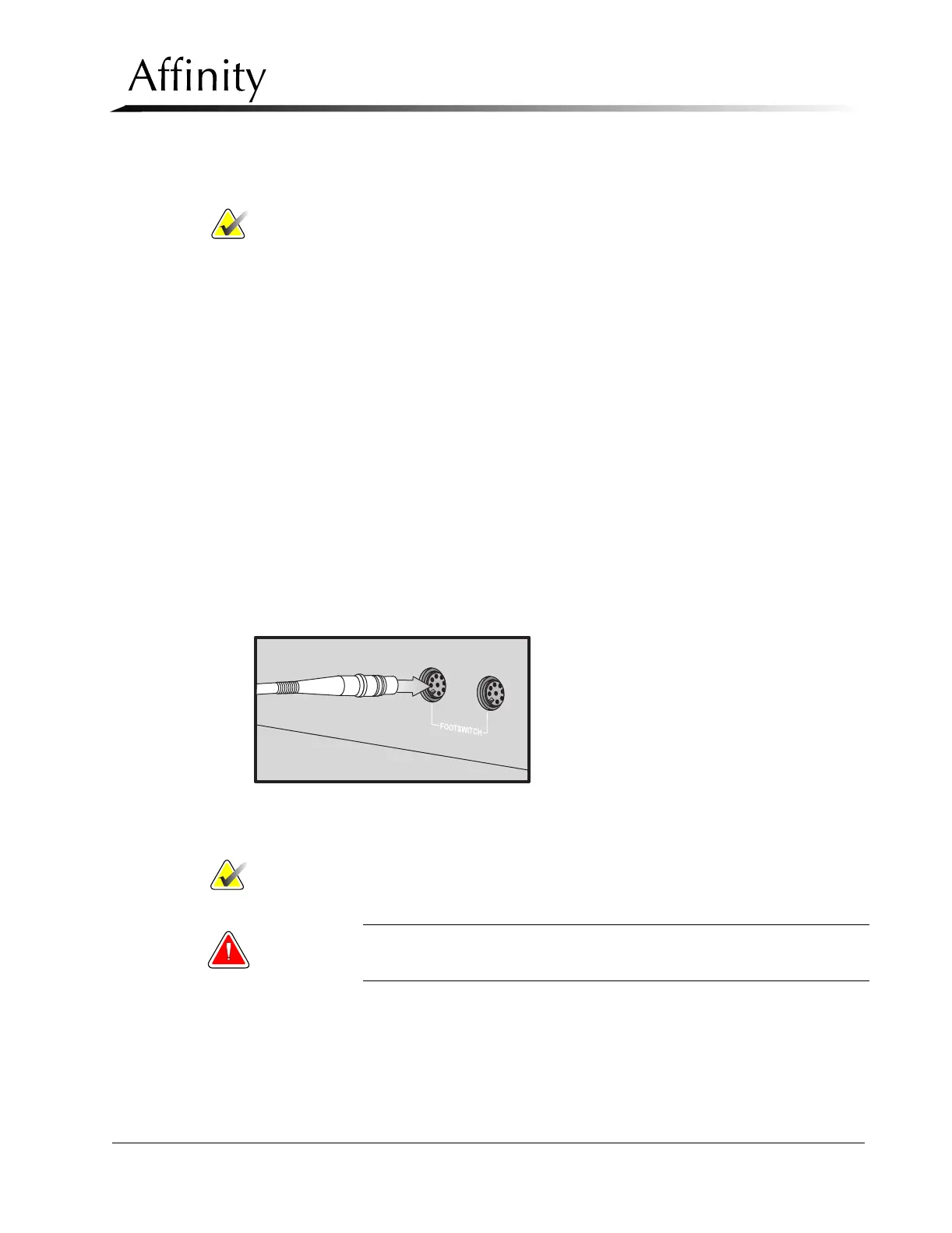
2. Align the key in the footswitch connector to the keyhole in the receptacle
(Figure 2-7).
Figure 2-7: Connecting a Footswitch
3. Push the connector straight in until it stops.
Note… Either Footswitch can be connected to either Footswitch receptacle.
4. Position the footswitch in the desired location on the floor below the C-arm.
WARNING: Position the Footswitch(es) in such a way as to prevent accidental
activation by patients or operators.