6-18 P/N 9-500-0255
Service Manual
Chapter 6: Maintenance—Remove and Replace Procedures
Gantry Components—Remove and Replace
2.5.2 Firmware Replacement
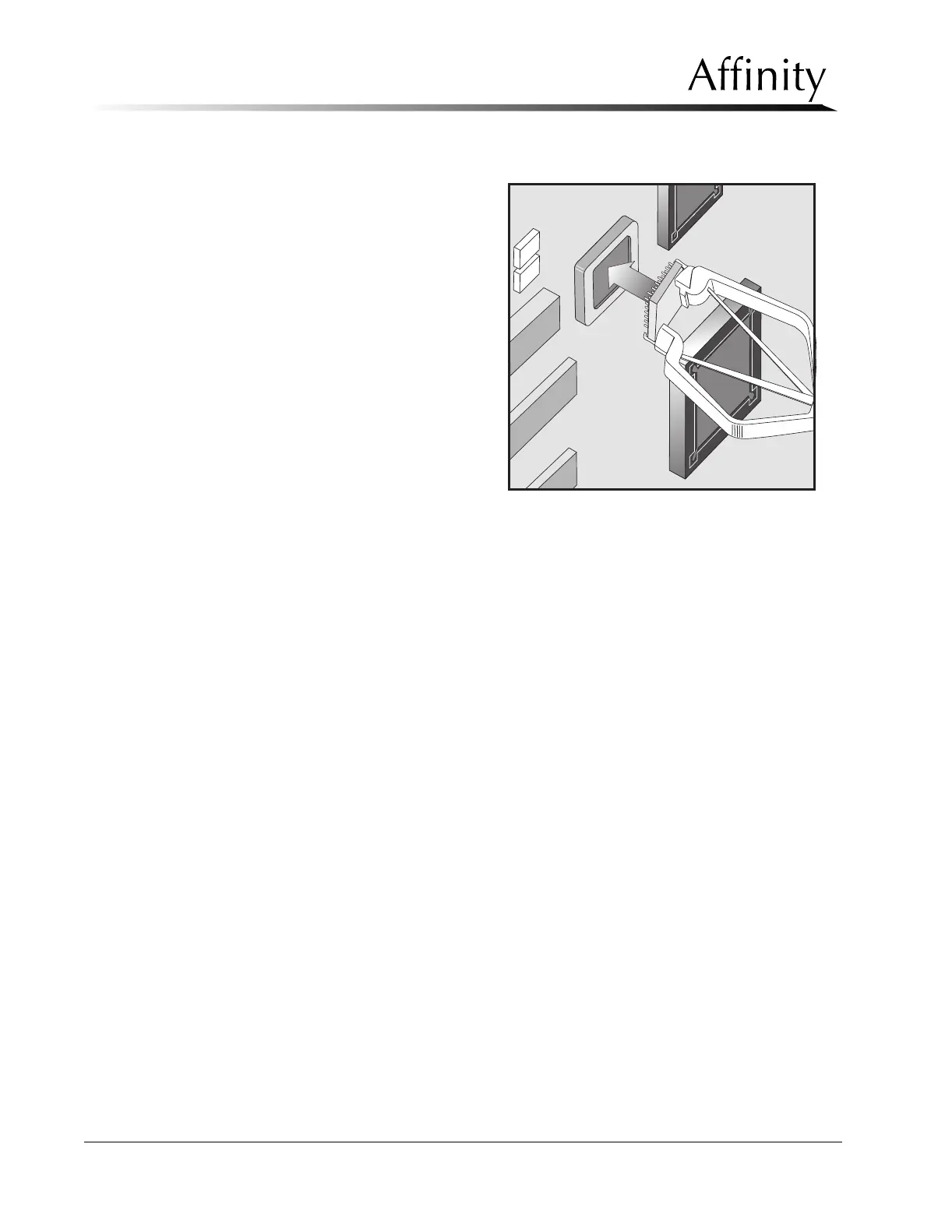
1. Using a PLCC chip remover,
gently pry the firmware
chip out of the socket (see
Figure 6-9).
2. Install the replacement
firmware chip into the
socket. Be sure to align the
dot on the chip with the
arrow in the socket.
2.5.3 Communications Interface Board
The Communications Interface Board is mounted to the right side Gantry frame, just
below the Microprocessor Board.
1. Remove power to unit and access the Communications Interface Board by
removing the right side Gantry cover as per Section 2.1.1.
2. Remove the wire harness connectors from their jacks at EJ1 through EJ16, and at
EJ19.
3. Lift the board off of the 6 “squeeze” type standoffs.
4. Reverse these steps to install the replacement board.
Figure 6-9: Microprocessor Firmware Chip—
Replacement