6-34 P/N 9-500-0255
Service Manual
Chapter 6: Maintenance—Remove and Replace Procedures
C-Arm Components—Remove and Replace
3.1.6 C-arm Switch Interface Board
The C-arm Switch Interface Board (Figure 6-15, Item 5) is mounted to the C-arm
frame, and is accessed by removing the Left Side C-arm Cover. This circuit board is
the interface between the five C-arm Switch Boards and the Affinity Series
Microprocessor.
1. Remove power from the unit. Remove the C-arm Bottom Cover as per Section
3.1.2.
2. Remove the left side C-arm Side Cover as per Section 3.1.2. Disconnect the
wiring harness from the upper and lower switch pad connectors. Set the cover
aside.
3. Disconnect the wiring harness from the jacks at NJ1, NJ2, NJ4, NJ5, NJ6 and
NJ7.
4. Remove the board from the plastic “snap” standoffs.
5. Reverse this procedure to install the replacement C-arm Switch Interface Board.
When complete, perform the C-arm Switch Functional Check as per Chapter 3,
Table 3-1, “Post Power-Up Checks”.
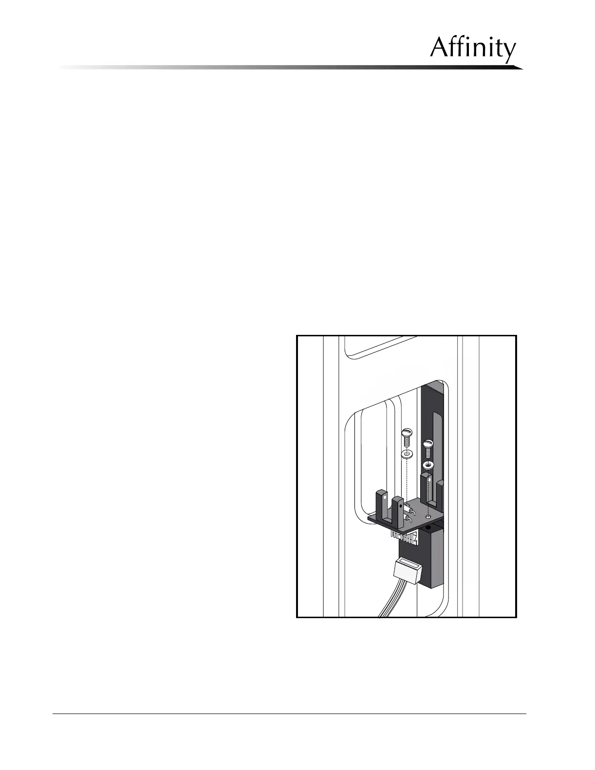
3.1.7 C-arm Accessory Detect Board
The C-arm Accessory
Detect Board (refer to
Figure 6-23) is mounted to
the C-arm frame, and is
accessed by removing the
Left Side C-arm Cover. This
circuit board - which
houses two optical sensors
- detects when a
magnification platform or
a stereotactic accessory (if
available) is installed.
When a magnification
accessory is installed, the
“MODE =” data field on
the Run Mode Screen will
read “MAG MAN”. When
a stereotactic accessory is
installed, the “RECEPTOR
=” data field on the Run
Mode Screen will read
“STEREO” and the “MODE
=” data field will read
“MANUAL”.
1. Remove power from
the unit. Remove the
C-arm Bottom Cover
as per Section 3.1.2.
2. Remove the left side C-arm Side Cover as per Section 3.1.2. Disconnect the
wiring harness from the upper and lower switch pad connectors. Set the cover
aside.
Figure 6-23: C-Arm Accessory Detect Board—Removal