P/N 9-500-0255 B-11
Service Manual
Appendix B: Technical References
Jumpers
6.0 Jumpers
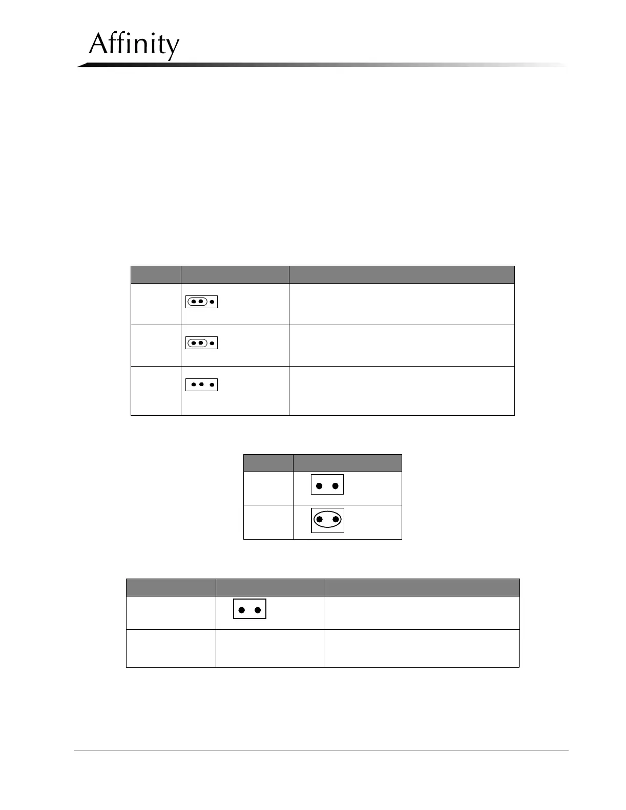
The following tables show the Jumpers on the Affinity boards with the default (factory setting) configuration. The
jumpers should not be changed from the configuration shown unless directed to do so during a test, or calibration
procedure. Any time the jumper setting is changed, it must be returned to the default position unless the change
was made to establish new operating parameters.
• Table B-21 - Microprocessor Board (PN 1-003-0493) Jumper Settings
• Table B-22 - Communications Interface Board (PN 1-003-0434) Jumper Settings
• Table B-23 - C-Arm Safety Board (PN 1-003-0440) Jumper Settings
• Table B-24 - HV Control Filament Board (PN 1-003-0485) Jumper Settings
Table B-21: Microprocessor Board (PN 1-003-0493) Jumper Settings
Table B-22: Communications Interface Board (PN 1-003-0434) Jumper Settings
Table B-23: C-Arm Safety Board (PN 1-003-0440) Jumper Settings
Jumper Default Setting Function
JP5 Backup Timer Test
(See Chapter 4, Section 4.4, Backup Timer Test.)
JP6 Backup Timer Test
(See Chapter 4, Section 4.4, Backup Timer Test.)
JP7 Select X-Ray ON/Boost ON for X-ray ON Lamp Instal-
lation
(See Chapter 2, Section 3.3, Remote X-ray ON/Power
ON Light Connection, for operational settings.)
Jumper Default Setting
JP1
JP2
Jumper Default Setting Function
JP1 Normal Operation
TP17 to TP16
Open
Default setting is for normal operations.
Short TPs together to for C-Arm Safety Board
Calibration (See Chapter 4, Section 8.4)
1 2 3
1 2 3
1 2 3
1212
1212
1212