4-22 P/N 9-500-0255
Service Manual
Chapter 4: Calibrations and Performance Checks
Automatic Exposure Control System Calibration
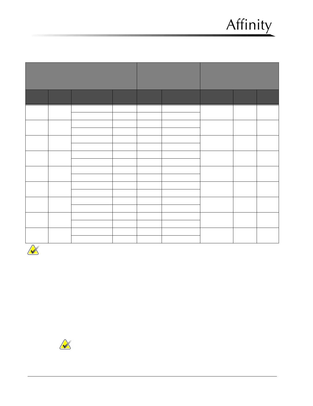
Table 4-6: AEC Performance Worksheet—Large Focal Spot, Mo Filter
5.9 Performance Test—Large Focal Spot (Rh)
This procedure ensures that the AEC system consistently produces films at the required
optical density (within 0.15 OD) using the Rh filter.
1. Select the Rhodium filter (refer to Table 4-7: AEC Performance Worksheet—Large Focal
Spot, Rh Filter).
2. Make Rh filtered exposures at 28 through 32 kV. Check the optical density of each film
to ensure that it is within ±0.15 OD of the mean optical density.
3. If necessary, make Gain and Offset adjustments. Use absorber thicknesses to make Gain
adjustments between 40 and 80 mAs. Use absorber thicknesses to make Offset adjust-
ments between 200 mAs and 350 mAs.
Note… It may be necessary to use absorber thicknesses greater than 6.0 cm to
achieve the desired mAs when calibrating AEC using the Rhodium filter at
higher kVs.
Large Focal Spot
0.030 mm Molybdenum Filter
18 x 24 cm Bucky/
Paddle/BR-12
KODAK MIN-R-2000
Film/Cassette
Gain - Lower Thickness = 40 to
80 mAs
Offset - Higher Thickness = 240
to 350 mAs
kV mA Recommended
Thickness
mAs OD Gain/Offset Max/-1.0 cm mAs OD
24 95 3.0 cm G=
4.0 cm
24 95 5.0 cm O=
25 100 3.5 cm G=
4.5 cm
25 100 5.5 cm O=
26 100 4.0 cm G=
5.0 cm
26 100 6.0 cm O=
27 100 4.0 cm G=
5.5 cm
27 100 6.5 cm O=
28 100 4.5 cm G=
6.0 cm
28 100 7.0 cm O=
29 100 4.5 cm G=
6.5 cm
29 100 7.5 cm O=
30 100 5.0 cm G=
7.0 cm
30 100 8.0 cm O=
31 100 5.0 cm G=
7.5 cm
31 100 8.5 cm O=
32 100 5.5 cm G=
8.0 cm
32 100 9.0 cm O=
Note… Adjust thickness as necessary to achieve desired results.