2-8 P/N 9-500-0255
Service Manual
Chapter 2: System Installation
Unit Installation
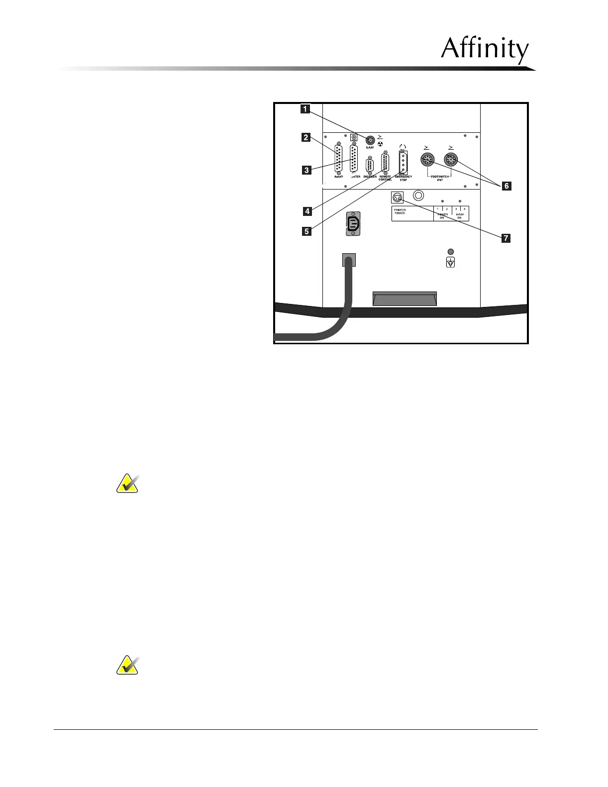
Legend for Figure 2-6
1. Exposure Footswitch
Connector
2. Rapid I.D. Receptacle
3. Printer/AutoFilm I.D.
Connector
4. Remote Control
(remotely located Con-
trol Panel
5. Emergency Stop
6. Footswitch Connectors
7. AutoID/Rapid ID
Power Outlet
3.5 Securing Unit in Position
1. Remove left and right Gantry side panels as per Chapter 6, Section 2.1.1.
2. Carefully move the unit into its pre-designated final position. Ensure the circuit breaker
and rear panels are accessible.
3. Mount unit to the floor in accordance with site specification drawings and/or local
building codes.
Note… Do not replace left and right side panels at this time.
3.6 Installing the Unit Accessories
This section provides instructions for installing the following accessories:
• Exposure Footswitch
• Dual Function Footswitch(es)
• Film Labeling Devices
3.6.1 Exposure Footswitch
When the exposure footswitch is installed on a machine, you must push both the
exposure footswitch and the x-ray button on the control panel at the same time to
initiate and finish an exposure.
Install the exposure footswitch as follows:
Note… The exposure footswitch will be received already mounted on the exposure
footswitch mounting bracket.
Figure 2-6: Rear Connector Panel (Shroud removed) and
Lower Rear Panel Connections