P/N 9-500-0255 6-53
Service Manual
Chapter 6: Maintenance—Remove and Replace Procedures
C-Arm Components—Remove and Replace
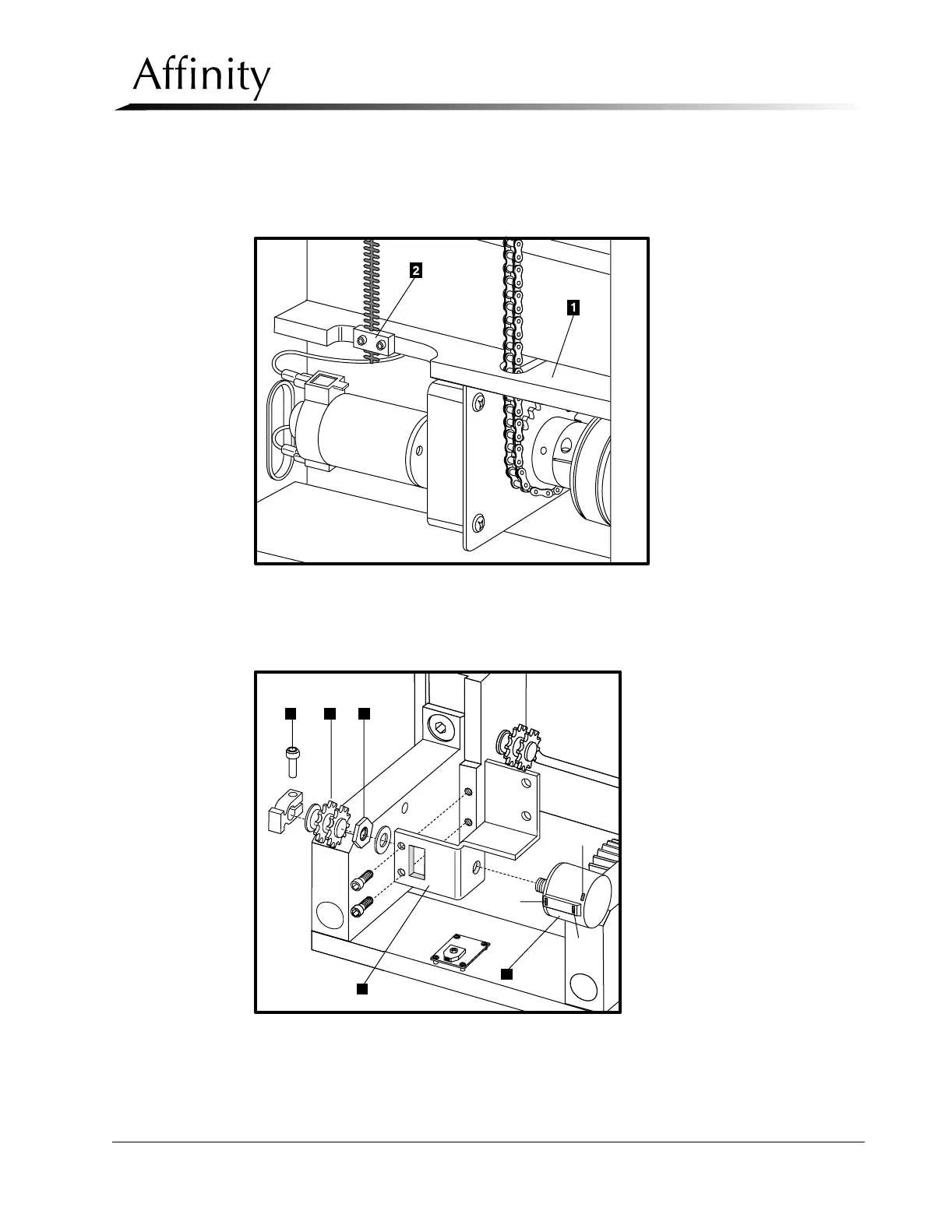
Legend for Figure 6-35
1. Bearing Block Assembly
2. Lower Clamp Block
Figure 6-36: Removal of Timing Belt from Bearing Block Assembly
8. Locate 3 colored wires soldered to potentiometer. Note the colored wire for
each post and desolder wires. Refer to Figure 6-37.
Figure 6-37: Compression Thickness Potentiometer—Removal
9. Remove screws from potentiometer bracket and pull from compression device.
1 3 4
2
5
Pin 2
Pin 1
Pin 3