6-6 P/N 9-500-0255
Service Manual
Chapter 6: Maintenance—Remove and Replace Procedures
Gantry Components—Remove and Replace
4. Disconnect the wiring harnesses from their receptacles. Tag each connector
with its receptacle designation.
5. Pull the chassis completely out of the Gantry.
6. Reverse these procedures to replace the panel.
2.2 Gantry Cover Components
2.2.1 C-arm Angle Display Boards
The Affinity Series has two C-arm Angle Display Boards which are mounted inside
the left and right side Gantry covers, near the top. The removal procedure for both
boards are identical.
1. Remove power to the unit. Remove the left or right side Gantry cover (which-
ever is appropriate).
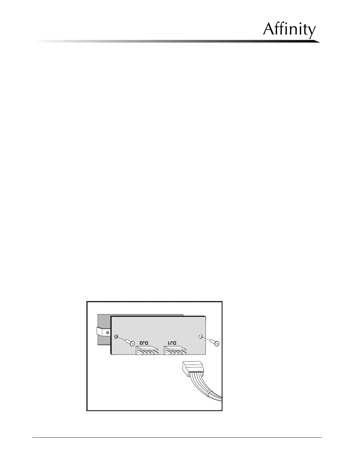
2. Locate the connector at DJ1 on the rear of the C-arm Angle Display Board and
disconnect it.
3. Remove the two mounting screws that secure the Display Board to the cover.
Pull the board off of the spacers. Note that the two spacers between the board
and the mounting holes can be removed.
4. Position the replacement C-arm Angle Display on top of the spacers. Secure the
board and spacers with the previously removed hardware.
5. Make the wire harness connection at DJ1 on the Board. Apply power to the
system, then rotate the C-arm to the 0° position.
6. Verify that both C-arm Angle Displays read 0°.
7. Check that both C-arm Angle Displays show the correct C-arm angle at ±45°,
±90°, ±135°, and +180° when moved to each detent position.
8. If the test fails, check the C-arm Detent Microswitch adjustment and the C-arm
Rotation Potentiometer adjustment (later in this section).
9. When complete, turn the unit off, then replace the previously removed cover.
Figure 6-4: C-arm Angle Display Board—Removal