4-16 P/N 9-500-0255
Service Manual
Chapter 4: Calibrations and Performance Checks
Automatic Exposure Control System Calibration
8. On the Microprocessor board, verify jumpers are positioned as follows (if not, install
jumpers):
• JP5 between positions 1 and 2
• JP6 between positions 1 and 2
9. Install a DIP clip on U20 and connect scope lead to Pin 2. Connect the ground lead to
TP12 (DGND).
10. Turn the Unit ON.
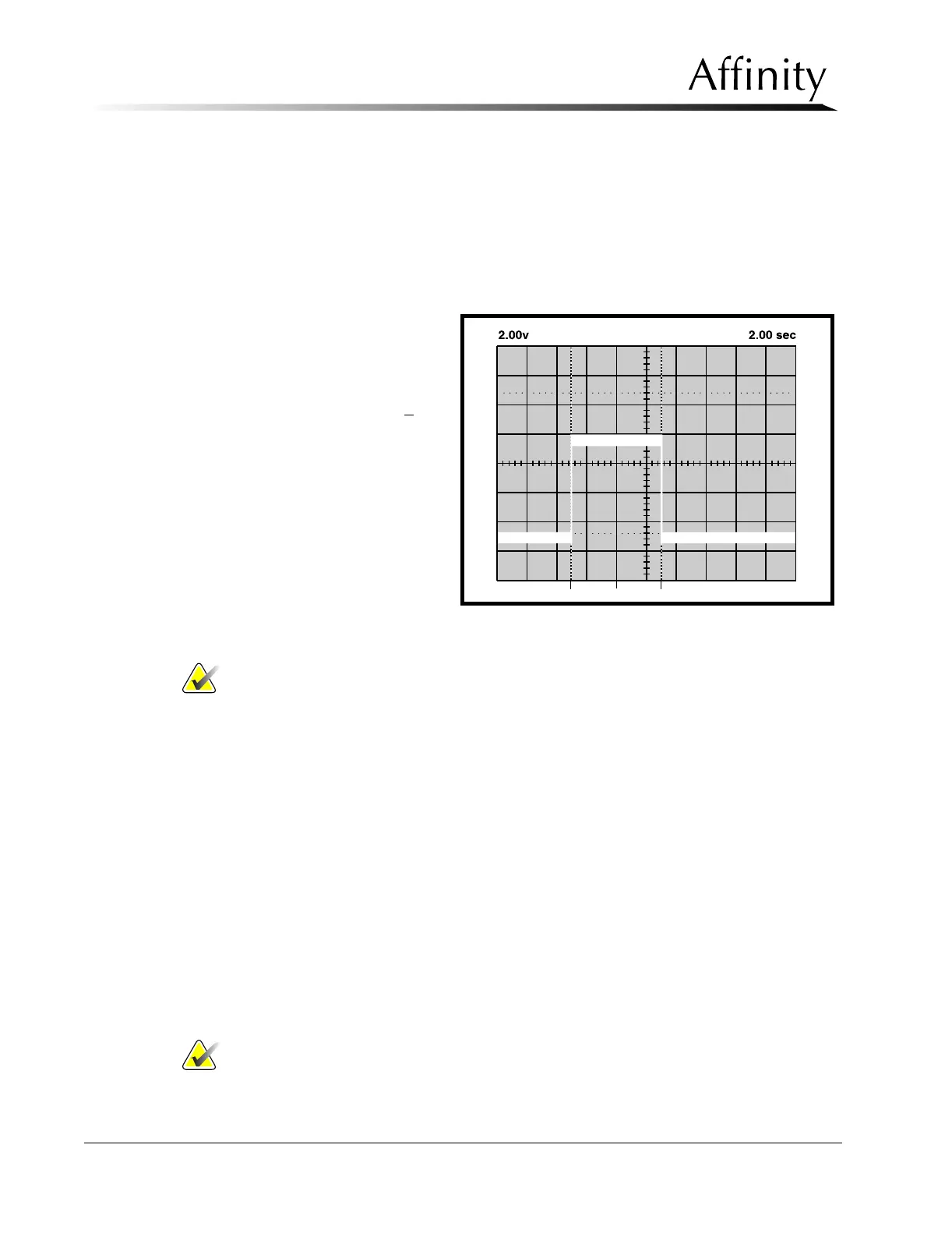
11. Set up scope as follows:
• Volts/DIV : 2.00 V
• Time/DIV: 2.00 sec
• Mode : AUTO
12. Set the time-out to 6.3 +
0.25
seconds as follows (refer to
Figure 4-5):
a. Trigger the IC by
momentarily short-
ing U11 Pin 1 to
U11 Pin 2.
b. While viewing sig-
nal on scope, adjust
Pot R146.
Note… During the next step, the unit will not take X-rays and will attempt a 7.0 sec
exposure.
13. Initiate an exposure.
14. When the exposure terminates, the message area along the lower part of the screen indi-
cates the exposure duration (when the timer terminated the exposure), and the status of
the test.
15. Verify that the test “PASSED”. If the indication is “FAILED”, contact L
ORAD Service
department immediately. Do not use the system clinically.
16. The Timer Test field will automatically reset to OFF.
17. Remove all test equipment, do not remove jumpers JP5 and JP6.
18. Return the unit to the user mode (S2 switch 1 = OFF) and replace previously removed
panels.
5.0 Automatic Exposure Control System Calibration
The following sub-sections are provided to calibrate the Automatic Exposure Control (AEC)
System. Be sure the Exposure Generating System (kV & mA) is properly adjusted prior to
calibrating AEC.
Note… AEC adjustment may be required if film or film cassettes, chemistry, or
processor settings (i.e., temperature or replenishment rates) have been
changed.
Figure 4-5: Example—Backup Timer Time-out Signal