6-12 P/N 9-500-0255
Service Manual
Chapter 6: Maintenance—Remove and Replace Procedures
Gantry Components—Remove and Replace
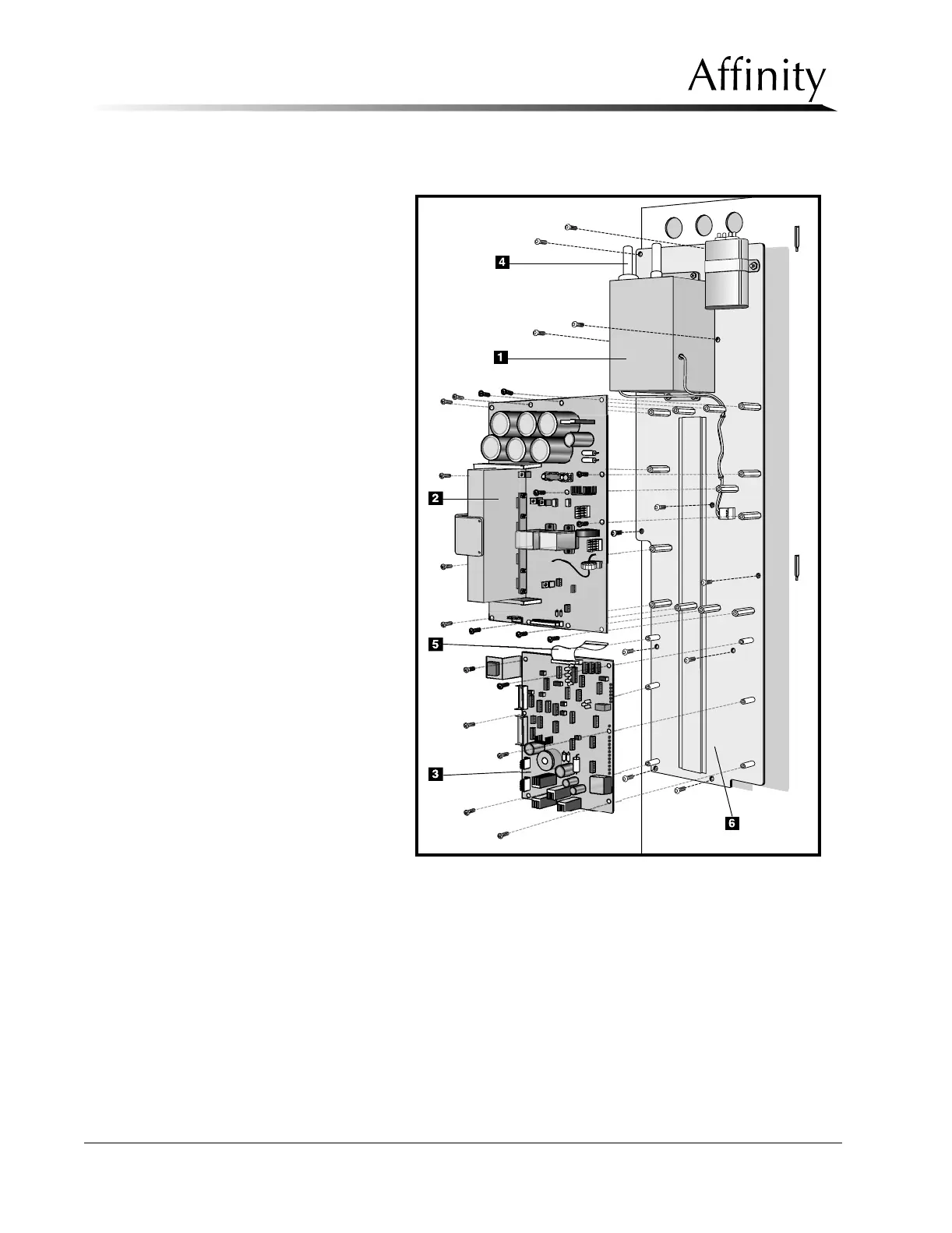
F. On the HV Control Filament board, disconnect MJ1, MJ2, MJ4, MJ5, MJ6,
MJ7 and MJ8.
G. Remove the 6 screws securing the HV Control Filament board to the stand-
offs on the mounting plate. Remove board from standoffs and set aside.
H. Remove the 13 screws securing the HV Inverter board to the standoffs on
the mounting plate. Remove board from standoffs and set aside.
I. Locate and remove the 5 phillips screws securing the lower portion of the
mounting plate to the Gantry frame.
Legend for Figure 6-7
1. HV Multiplier
2. HV Inverter Board
3. HV Control Filament Board
4. HV Cable Receptacle
5. Ribbon Cable
6. Mounting Plate (old style)
Figure 6-7: HV Generator Assembly (old style mounting
plate)—Removal