P/N 9-500-0255 6-23
Service Manual
Chapter 6: Maintenance—Remove and Replace Procedures
Gantry Components—Remove and Replace
2.6.4 The C-arm Vertical Drive Actuator
The C-arm Up/Down Actuator assembly is mounted on the unit base inside the
Gantry. Access to the entire assembly requires removal of the rear Gantry panels.
Remove the C-arm Vertical Drive Actuator as follows:
1. Remove the Upper Rear Gantry Panel (Section 2.1.2), the Rear Connector Panel
(Section 2.1.3) and the Lower Rear Panel (Section 2.1.4).
2. Apply power to
the system.
3. Raise the C-arm
completely. If
unable to raise the
C-arm using the
controls (due to
motor failure),
raise C-arm
manually.
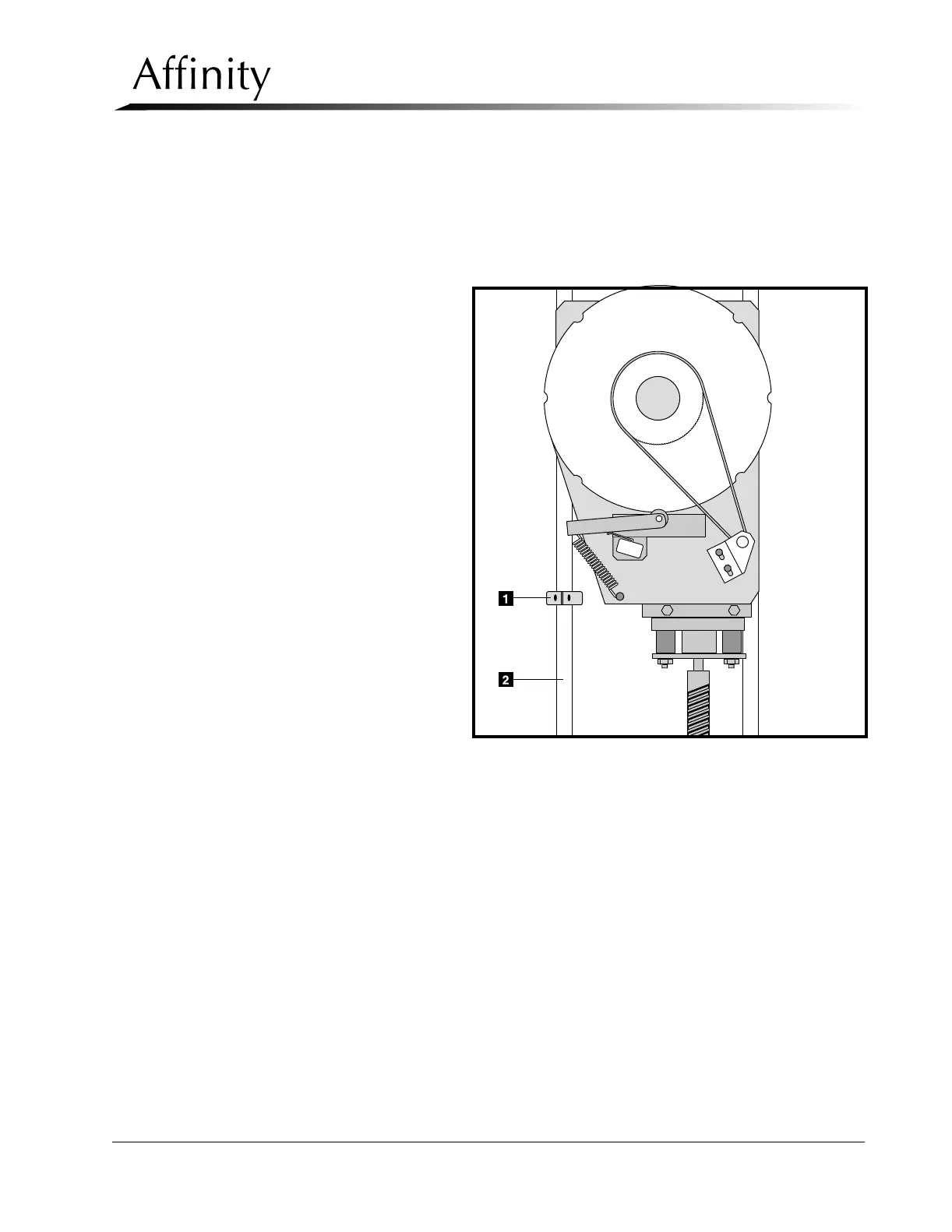
1. Secure a shipping
collar (Figure 6-
13, Item 1), one
can be obtained
through L
ORAD
Service depart-
ment, to the right
VTA rail (Figure 6-
13, Item 2) (on the
left as seen from
the rear of the
Gantry) as shown
in Figure 6-13.
Figure 6-13: Shipping Collar Installation of VTA Rail
2. Lower the C-arm until it stops on the collar.
3. Remove hub nut screws (Figure 6-14, Item 11) and lower hub nut (Figure 6-14,
Item 9) by hand.
4. Turn the system Off.
5. Unplug the 4-pin connector from the C-arm drive actuator motor.
6. To release the lower portion of the actuator (Figure 6-14, Item 1), pull out the
spring clip (Figure 6-14, Item 2) in the end of the clevis pin (Figure 6-14, Item 3),
then pull the clevis pin from the isolation mount (Figure 6-14, Item 4).
7. Loosen the screw that fastens the jam nut bracket (Figure 6-14, Item 5) to the
jam nut (Figure 6-14, Item 6), then remove the screw that fastens the bracket to
the standoff (Figure 6-14, Item 7) on the lower portion of the VTA isolation
mount (Figure 6-14, Item 8).
8. Thread the jam nut down 3 to 4 inches.
9. Remove the two screws that secure the hub nut (Figure 6-14, Item 9) to the VTA
isolation mount, then thread the hub nut down to the jam nut.