P/N 9-500-0255 6-57
Service Manual
Chapter 6: Maintenance—Remove and Replace Procedures
C-Arm Components—Remove and Replace
3.4.4 Accessory Detect Board
The Accessory Detect board (Figure 6-40, Item 2) is mounted to the bottom side of
the IRSD top plate. Access to this component requires removal of the IRSD covers.
1. Turn power OFF. Remove the IRSD covers as per Section 3.4.1, then flip the alu-
minum top plate over to access the detector board.
2. Remove the wiring harness from the connector on the detector board.
3. Loosen and remove the 4 screws that secure the board to the standoffs. Lift the
board off the top plate.
4. To install the replacement Accessory Detector board, reverse these steps.
5. Set the top plate onto the IRSD frame, then apply power and enter the Run
Mode. Using the Image Receptor Phantom Tool (PN 9-060-0403) or reflective
tape, block the detectors according to the reference table in Appendix B (Table
B-19). Verify that the image receptor status on the LCD display changes
appropriately.
6. To install the replacement AEC Sensor board, reverse these steps. When
complete, perform the procedures listed below before releasing the unit to the
user:
• Chapter 4, Section 5.0, Automatic Exposure Control System Calibration
• Chapter 4, Section 6.10, IRSD Leakage Check
7. When complete, turn power off, then re-assemble the IRSD and replace the
covers.
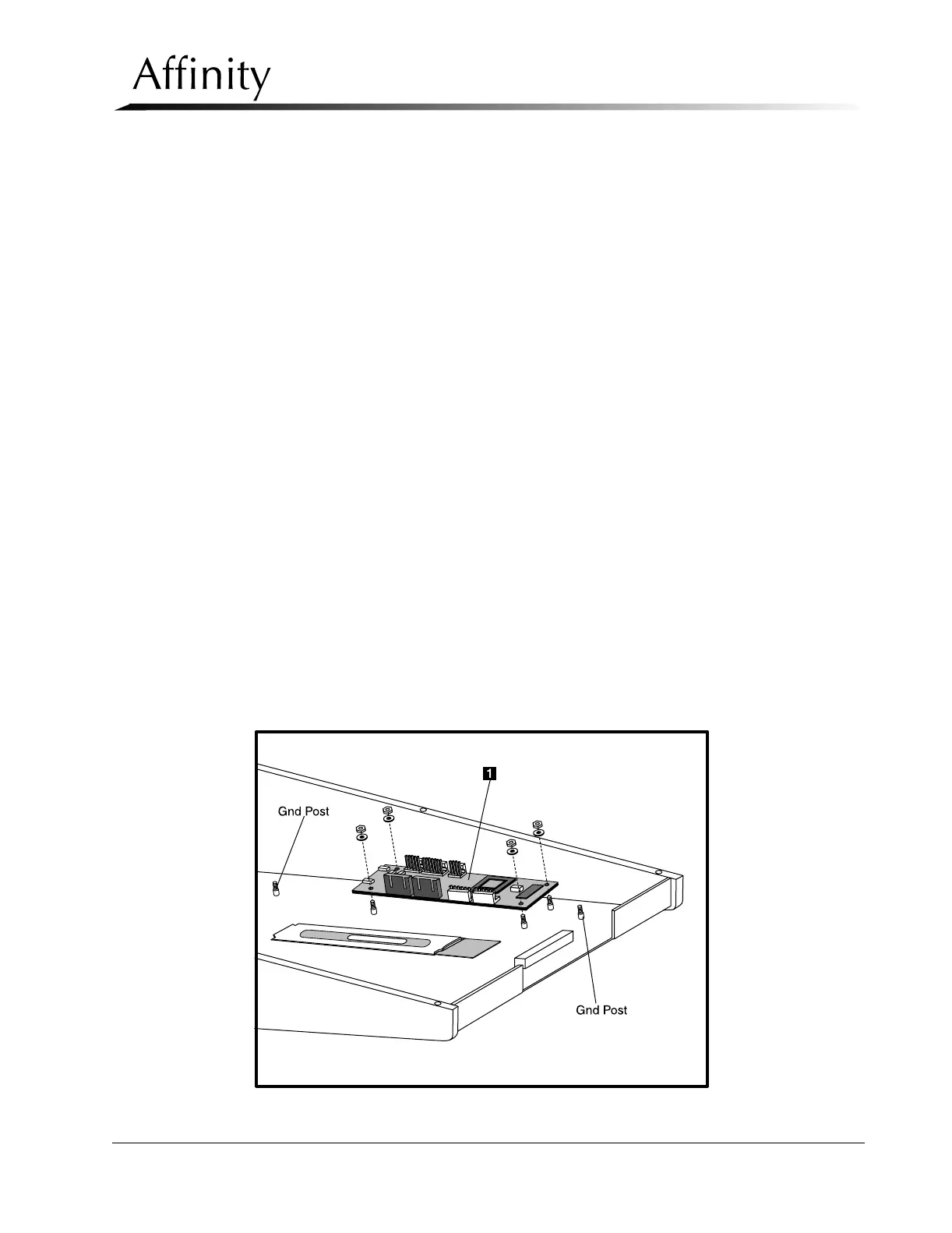
3.4.5 AEC Position Compression Display Microprocessor Board
The AEC Position Compression Display Microprocessor Board (Figure 6-41) is
mounted to the inside of the IRSD bottom plate. Access to this component requires
removal of the IRSD covers.
Figure 6-41: AEC Position Comp. Display Microprocessor—Removal