P/N 9-500-0255 3-1
Service Manual
Chapter 3: Functional Checks/Setting Defaults
Controls and Indicators
Chapter 3: Functional Checks/Setting Defaults
1.0 Controls and Indicators
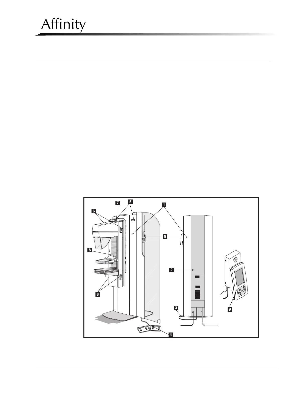
Figure 3-1 shows the location of the Affinity Series Controls and Indicators used throughout
this Chapter. For detailed information on the Affinity Controls and Indicators, refer to the
Affinity Series Operator’s Manual, PN 9-500-0246.
Legend for Figure 3-1
1. Emergency OFF Switches (EMO)—Two on front of Gantry, one on rear. (For those sys-
tems with the Remote Control Panel installed, a fourth EMO switch is located on the
control panel mounting block.)
2. Circuit Breaker
3. X-ray Footswitch
4. Dual Function Footswitch
5. Rotation Angle Display
6. C-Arm Controls 7-Button Keypad (two top, two bottom)
7. Tubehead Controls 3-Button Keypad
8. Compression Device
9. Control Panel
Figure 3-1: Affinity Controls and Indicators