6-20 P/N 9-500-0255
Service Manual
Chapter 6: Maintenance—Remove and Replace Procedures
Gantry Components—Remove and Replace
2.6 Internal Gantry Components
Refer to Figure 6-1: Gantry Components, for location of internal gantry components
throughout the following subsections.
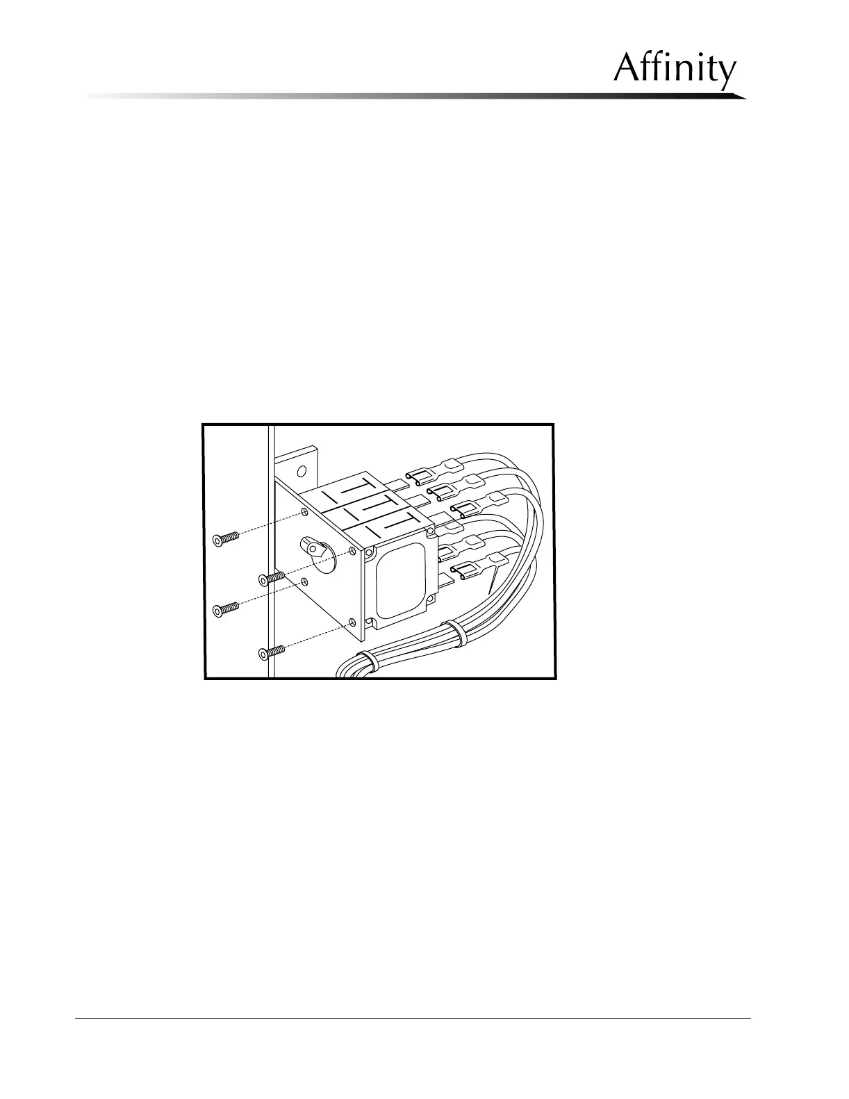
2.6.1 Main Circuit Breaker
The Power On/Off Circuit Breaker is accessed by removing the upper rear Gantry
panel.
1. Remove power to unit and access the Main Circuit Breaker by removing the
upper rear Gantry panel as per Section 2.1.2.
2. Remove the 4 screws that secure the Circuit Breaker to the mounting bracket
(see Figure 6-10).
3. Pull the Circuit Breaker out and disconnect the six wires from the lugs on the
rear of the relay. Note each wire color/lug position.
4. Reverse this procedure to install the replacement Circuit Breaker.
Figure 6-10: Main Circuit Breaker—Removal