P/N 9-500-0255 6-27
Service Manual
Chapter 6: Maintenance—Remove and Replace Procedures
C-Arm Components—Remove and Replace
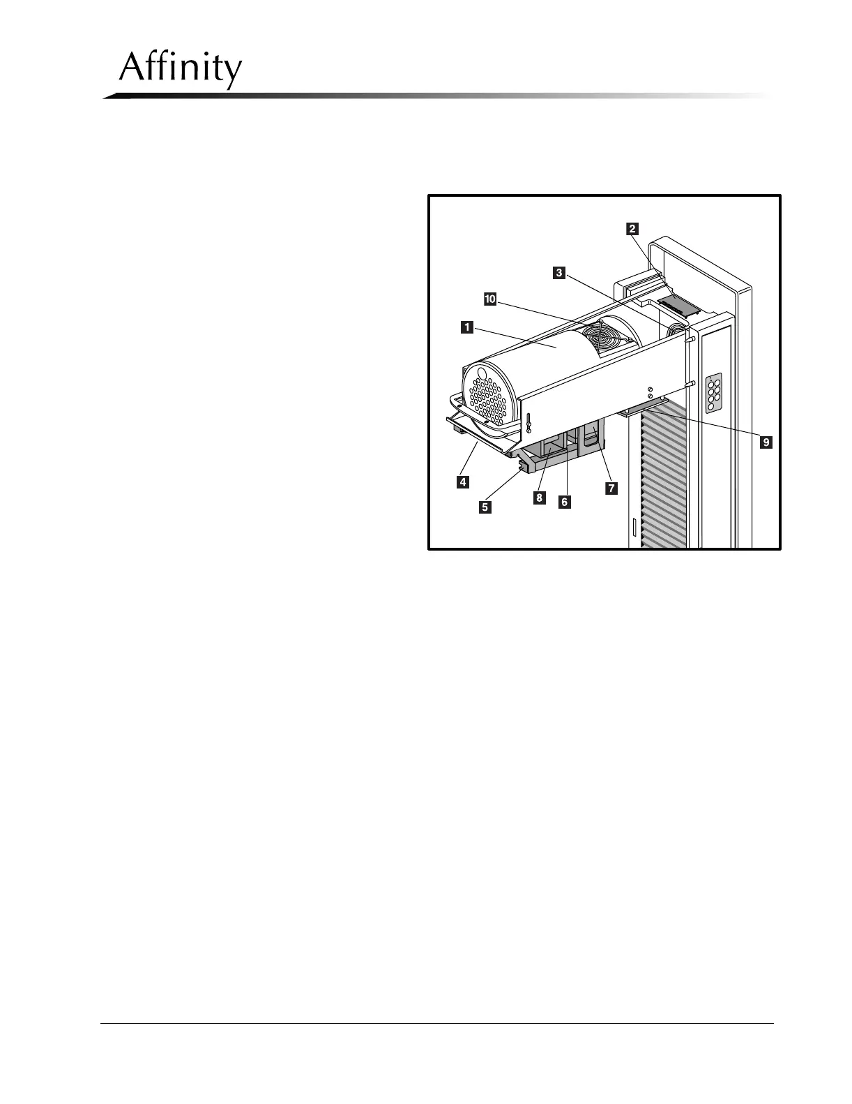
Use the following legend and illustration as a guide for parts identification on the Tubehead
and on the Beam Limiting Assembly (refer to Figure 6-16).
Legend for Figure 6-16
1. X-ray Tube
2. Filament Protect Board
3. C-arm Cooling Fan
4. Aperture Detect Board (part of
Beam Limiting Assembly)
5. Filter Shifter Assembly (part of
Beam Limiting Assembly)
6. Filter Position Detectors (part
of Beam Limiting Assembly)
7. Light Field Lamp Assembly
(part of Beam Limiting
Assembly)
8. Motorized Mirror Assembly
(part of Beam Limiting
Assembly)
9. Tubehead Control Board
10. Tube Fan
Figure 6-16: Tubehead / Beam Limiting Components
CM
M
o
R
h