2-6 P/N 9-500-0255
Service Manual
Chapter 2: System Installation
Unit Installation
3.3 Remote X-ray ON/Power ON Light Connection
The Affinity System provides the user with the ability to operate remote lights which
indicate when the System is ON and when X-rays are being taken. These lights are
normally installed above the door to the exam room. Installation should be done by a
certified electrician. The relay contacts provided are rated as follows:
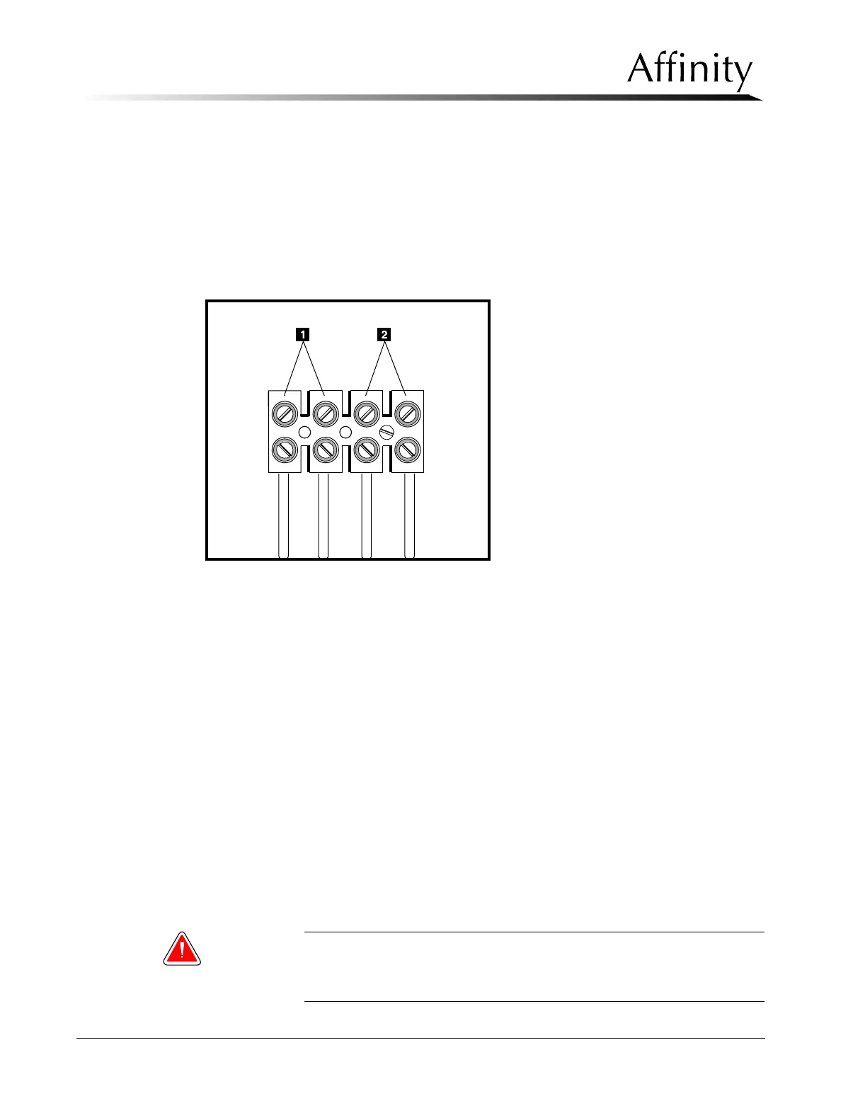
Legend for Figure 2-4
1. X-ray ON Lamp Connections
2. Power ON Lamp Connections
Figure 2-4: User Lamp (X-ray ON/Power ON) Connections
• 10 Amp 250 VAC (normally open)
• 10 Amp 30 VDC (normally open)
Connections are made on the removable power supply distribution assembly (Figure 2-4),
located on the input power assembly chassis, as follows:
1. Locate the removable power distribution assembly and connect the remote X-ray ON
and Power ON cables to the terminal board as shown in Figure 2-4.
2. Complete the remote cables and light installation following local guidelines.
3. Replace the Gantry lower rear, upper rear and rear connector panels. Do not replace
rear connector panel shroud at this time.
3.4 Control Panel Installation
The Control Panel is either mounted to the side of the Gantry or remotely located. Follow the
instructions appropriate for the site’s required configuration.
3.4.1 Control Panel to Gantry Installation
For Gantry mount configurations, the Affinity is shipped with the Control Panel
already attached to the right side cover.
Warning: For those units with the Control Panel mounted to the Gantry, the
radiation shield is required. The shield is installed following
completion of initial startup procedures.