P/N 9-500-0255 6-45
Service Manual
Chapter 6: Maintenance—Remove and Replace Procedures
C-Arm Components—Remove and Replace
3.2.11 Motorized Mirror Assembly
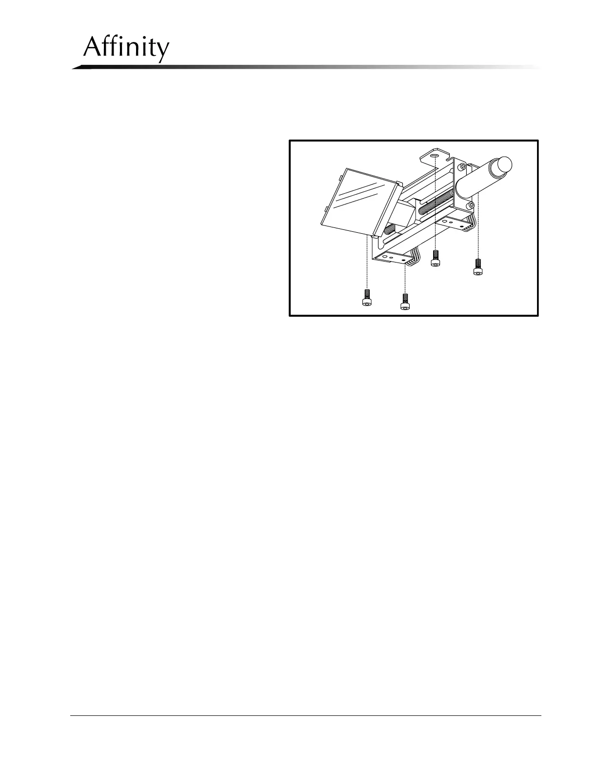
The Motorized Mirror Assembly (Figure 6-31) mounts to a bracket on the tubehead
chassis and is removed as an assembly.
1. Remove the
lower tubehead
cover as per
Section 3.2.1.
2. Disconnect the
wiring harness
from the
Tubehead
Control Board
(Figure 6-16).
Note locations.
3. Remove the 4
socket head
screws (Figure
6-31) that secure
the Motorized
Mirror Assembly
to the mounting bracket on the left side of the beam limiting device. Pull the
entire assembly from the unit.
4. Position the replacement Motorized Mirror Assembly in the mounting bracket
and secure it with the previously removed hardware.
5. Connect wiring harness to the Tubehead Control Board as noted in Step 2
above.
6. Apply power to the unit.
7. On the Tubehead Control Board (Figure 6-26), push S4 to cycle the mirror
assembly completely forward so that the flag blocks the front sensor. Verify that
D8 on the Tubehead Control Board illuminates momentarily.
8. Push S2 to cycle the mirror assembly completely back so that the flag blocks the
rear sensor. Verify that D9 on the Tubehead Control Board illuminates (stays lit).
9. Push S4 to cycle mirror assembly back to original position.
10. Set the unit for a short exposure. Verify that the mirror cycles out of the x-ray
field before the exposure, then cycles back over the tube port after the exposure.
11. When complete, install the tubehead covers.
Figure 6-31: Motorized Mirror Assembly—Removal