B-2 P/N 9-500-0255
Service Manual
Appendix B: Technical References
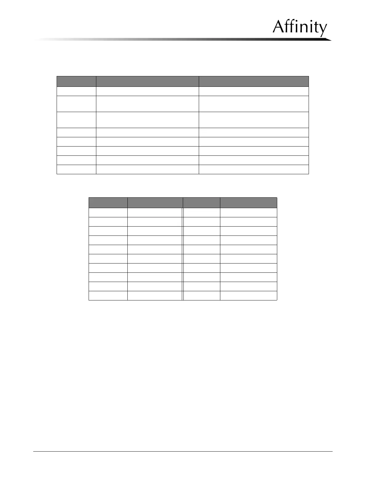
Test Points
Table B-2: Power Control Board (PN 1-003-0445) Test Points
Table B-3: C-arm Safety Board (PN 1-003-0440) Test Points
Test Point Voltage/Signal Function
TP1 Vref Active = 10.5 V
TP2 M+ Motor + = +11.7 V compression up; -11.7 V
compression down; Reference to TP3
TP3 M- Motor - = -11.7 V compression up; +11.7 V
compression down; Reference to TP2
TP5 Vcc +5 V
TP6 Sense Active = 200 mV
TP7 MGND ---
TP8 Vbb +13.6 V
TP9 VM +20 V
Test Point Voltage/Signal Test Point Voltage/Signal
TP1 Vref TP11 GND
TP2 Acc0 TP12 -12 V
TP3 Acc1 TP13 Vcc
TP4 Acc2 TP14 +5 V
TP5 Not Used TP15 -5 V
TP6 ACK OK TP16 TPY
TP7 DAC 1 TP17 TPX
TP8 DAC 0 TP18 Not Used
TP9 +5 V TP19 AGND
TP10 +12 V TP20 DGND