P/N 9-500-0255 6-35
Service Manual
Chapter 6: Maintenance—Remove and Replace Procedures
C-Arm Components—Remove and Replace
3. Disconnect the wiring harness from the jack on the circuit board.
4. Remove the 2 screws that secure the detect board to the board mount on the C-
arm frame. Pull the board from the unit.
5. Install the replacement C-arm Accessory Detect Board by reversing this
procedure.
6. Apply power. Using a piece of paper or cardboard, block each sensor
individually and verify the Run Mode Screen changes accordingly.
3.2 Tubehead Components
This section details the removal and replacement procedures for the components inside the
tubehead assembly, including the x-ray tube and the beam limiting device. Alignment,
adjustment or calibration instructions are provided.
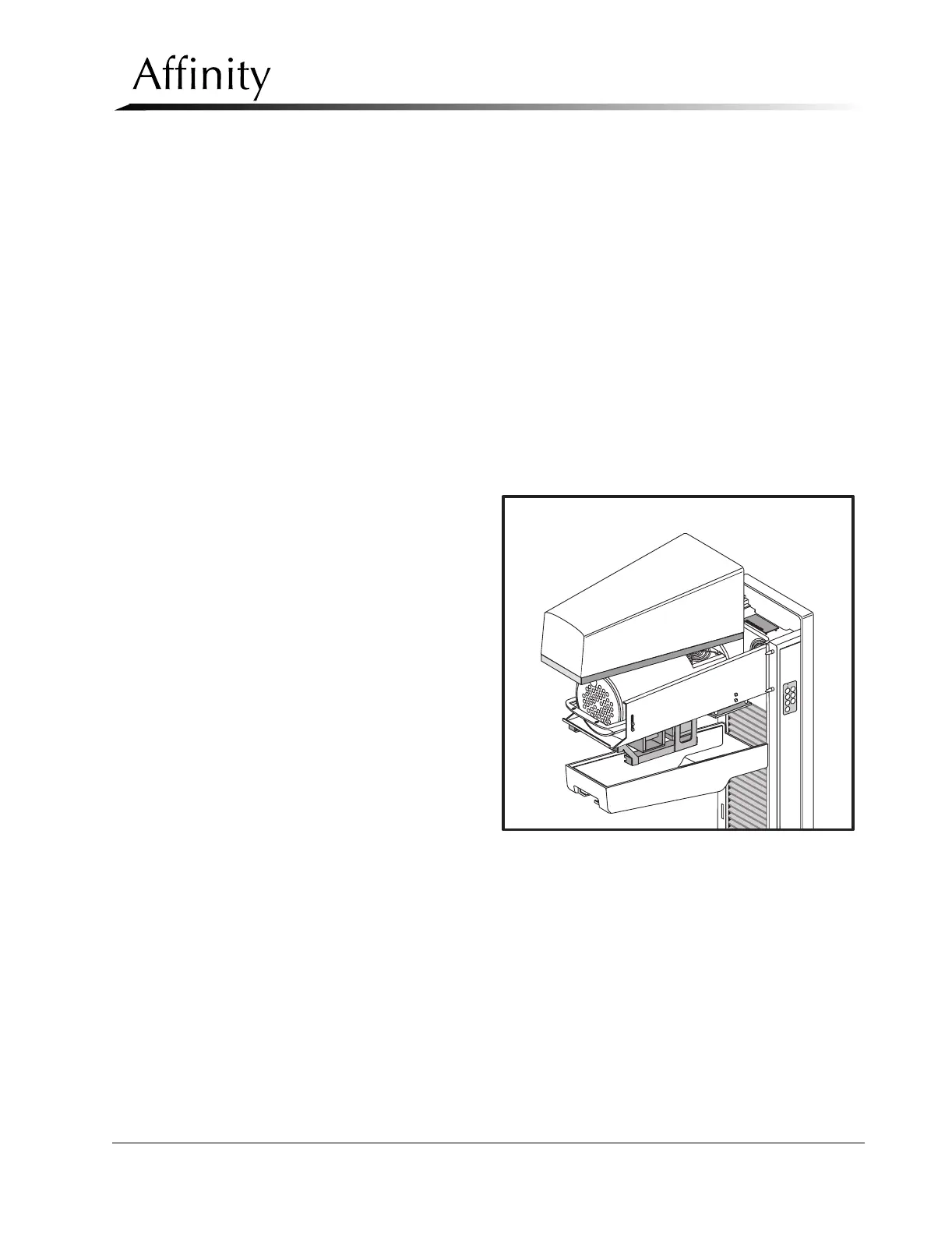
3.2.1 Tubehead Covers
The x-ray tubehead enclosure is comprised of an upper cover and a lower cover
(Figure 6-24). The lower cover must be removed first.
1. Remove power from
the unit. Remove the
aperture (if installed)
from the slit in the
tubehead.
2. Remove the screw that
secures the front of the
lower cover. This
screw is accessed from
the bevel in the
aperture slot.
3. Pull the front of the
lower cover down
slightly to free it from
the upper cover, then
pull it away from the
C-arm.
4. Remove the 2 screws
that secure the front of
the upper cover to the
tubehead chassis. Pull
the upper cover up and off of the C-arm until the alignment holes on the rear of
the cover clear the locating pins on the C-arm Frame.
5. Reverse these steps to install the upper and lower tubehead covers.
Figure 6-24: Tubehead Covers—Removal
C
M
M
o
R
h