6-2 P/N 9-500-0255
Service Manual
Chapter 6: Maintenance—Remove and Replace Procedures
Gantry Components—Remove and Replace
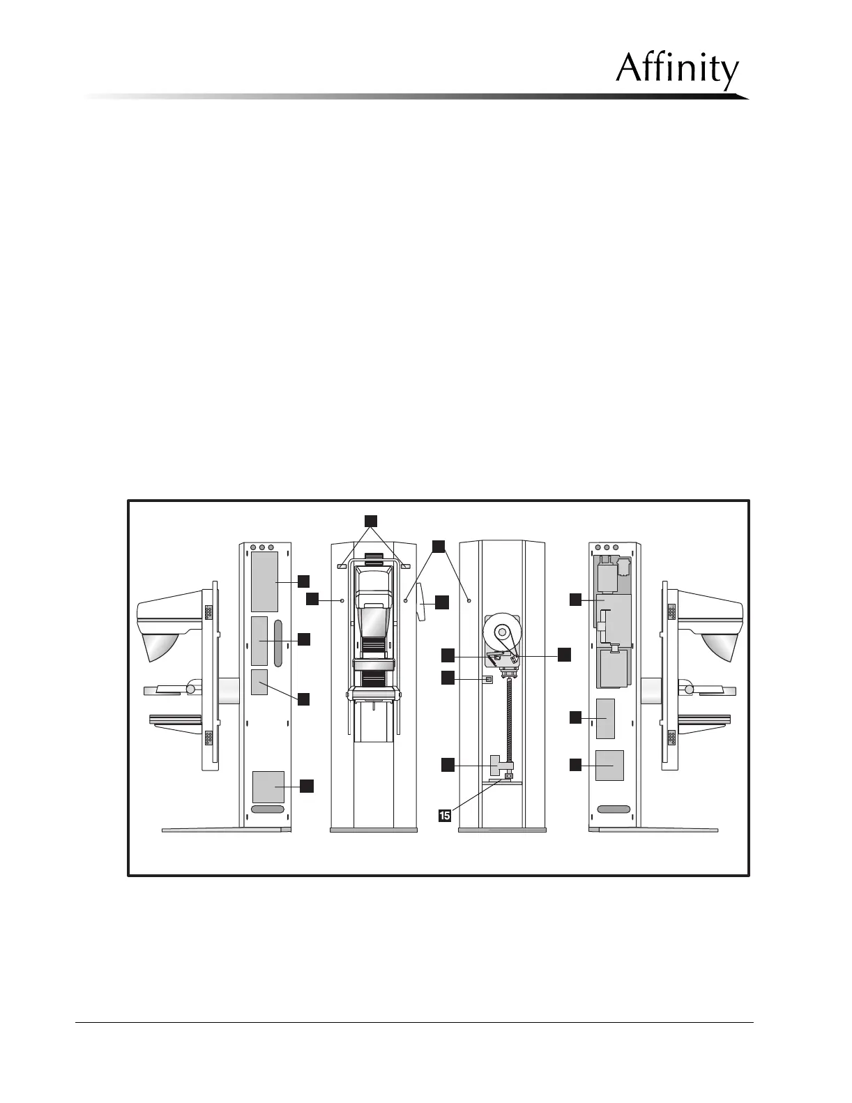
Legend for Figure 6-1
1. C-arm Angle Display Board (2)
2. Emergency Off Switch (3)
3. High Voltage Generator Assembly
4. Power Control Board
5. Auxiliary Power Distribution Board
6. Host Microprocessor Board
7. Communications Interface Board
8. Low Voltage Power Supply
9. C-arm Safety Board
10. Main Circuit Breaker
11. C-arm Angle Detent Microswitch
12. C-arm Rotation Potentiometer
13. C-arm Actuator Assembly
14. Operator Control Panel (Control Unit Assy)
15. Force Load Cell—Vertical Drive
Figure 6-1: Gantry Components
1
2
11
3
4
5
2
6
7
8
9
12
10
14
13