363-206-204
Equipment and Rear Access Cable Installation
Issue 9 October 1998
2-51
Note
:
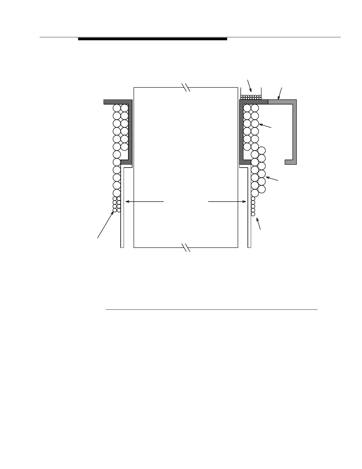
The cabling stacking order is shown above. The numbers on the cables
indicate the shelf associated with that cable.
Figure 2-2. ED-8C500 Frame, Rear Access Cable Placement
Office Alarms Mult
Assembly
Cables
Fiber
Optical
Order Wire Interface
X.25/TL1 Interface (6 max)
Modem
specified)
other shelves when
TBOS (Shelf #1 and
(Do not install cables
CIT, TBOS, Modem OUT Mult
groups of six.
bunched in
DS3/EC-1 Cables
Bay
Adjacent
DS1
DS1 Timing Mult
DS1 Timing
DDM-2000
Front of Bay
use.)
reserved for future
shelf. This space is
between bracket and
Office Alarms
Power
6
6
6
5
2
1
2
1
2
1
4
3
5
4
3
5
4
3
CIT, TBOS, Modem IN Mult
1
2
3
4
5
6
6
6
5
6
2
1
2
1
2
1
4
3
5
4
3
5
4
3
Misc. (Env.) Discrete Telemetry
Parallel Telemetry Mult
Parallel Telemetry