4-38
Issue 9 October 1998
363-206-204
Powering, Verification, and Circuit Pack Installation
Notes
:
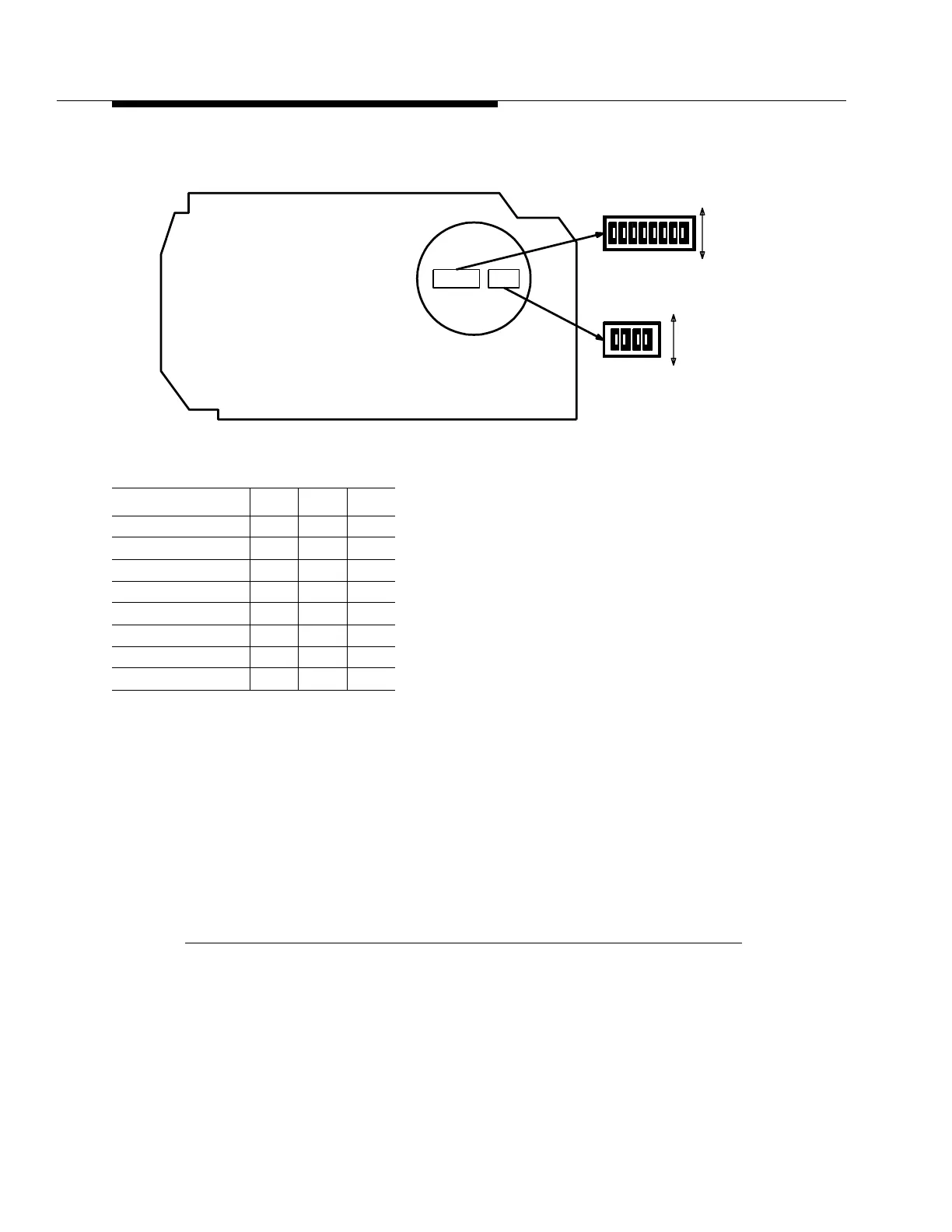
1. Switch S1 sets the network element number of the shelf. The network ele-
ment number and the site ID number form a unique address for a shelf at a
site. Obtain the network element number from the customer.
2. Switch 1, sections 6, 7, and 8 must be set to the ON position. Otherwise,
the FAULT LED on the OHCTL circuit pack will light and an alarm will be
generated.
3. Switch S2 is unused in early releases, but should be provisioned for section
1 set to ON and sections 2, 3, and 4 to OFF for ease of future upgrading.
Any subsequent settings should adhere to specific release specifications.
Figure 4-9. BBG7 (OHCTL) Option Switches (Sheet 1 of 3)
Switch 1 Settings
Network Element Sec 1 Sec 2 Sec 3
1 ON ON ON
2 OFF ON ON
3 ON OFF ON
4 OFF OFF ON
5 ON ON OFF
(Invalid) OFF ON OFF
(Invalid) ON OFF OFF
(Invalid) OFF OFF OFF
S2
S1
S1
Component Side
Connector
Edge
ON
S2
43
OFF
ON
21
876543
OFF
21