363-206-204
Equipment and Front Access Cable Installation
Issue 9 October 1998
3-31
NOTE
:
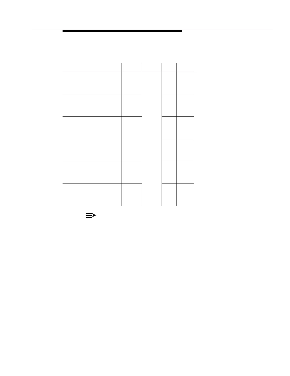
Parallel telemetry is not available in Release 13 software.
Notes
:
1. For ACO Control - Input, a pair of leads is connected between ACO-I and COM-I.
2. For all other parallel telemetry connections, a pair of leads is connected between the
telemetry point and COM-O (output-common).
3. The parallel telemetry cable is 26 gauge.
4. Some cables may be manufactured using wires following old color-code standards. A
color-code cross-reference is located in Table 3-9.
Table 3-7. Parallel Telemetry Connections
(See NOTE below.)
Name Desig. Conn. Term Color
ACO Control - Output
ACO Control - Input
Output - Common
Critical Alarm
ACO-O
ACO-I
COM-O
CR
J54 7
18
14
15
BR-W
R-BR
R-O
G-R
Major Alarm
Minor Alarm
Power Minor Alarm
Near-End Status
MJ
MN
PMN
NE
13
11
9
16
O-R
BL-R
S-W
R-G
Carrier Line Failure Status
Incoming Status
System Identifier - Shelf 1
System Identifier - Shelf 2
CLF
INCM
SID1
SID2
3
1
5
23
O-W
BL-W
G-W
O-BK
System Identifier - Shelf 3
System Identifier - Shelf 4
System Identifier - Shelf 5
System Identifier - Shelf 6
SID3
SID4
SID5
SID6
21
19
17
24
BL-BK
S-R
BR-R
BK-O
System Identifier - Shelf 7
Input - Common
Far End Site ID - Site 1
Far End Site ID - Site 2
SID7
COM-I
FE1
FE2
22
20
12
10
BK-BL
R-S
R-BL
W-S
Far End Site ID - Site 3
Far End Site ID - Site 4
Far End Site ID - Site 5
Far End Site ID - Site 6
FE3
FE4
FE5
FE6
8
6
4
2
W-BR
W-G
W-O
W-BL