4-32
Issue 9 October 1998
363-206-204
Powering, Verification, and Circuit Pack Installation
SYSCTL Switch 1 Notes
:
1. The TBOS display number is the order in which the shelves will report TBOS information
when prompted. Typically only point-to-point, odd numbered TBOS displays are in the
CO, and even-numbered TBOS displays are in the corresponding RTs.
2. The TBOS backup number is for shelves in a CO connected to TBOS. It prevents failure
of a single shelf in a bay from causing a TBOS link failure. The TBOS primary setting
assigns a shelf as a backup for a group of shelves that share the same TBOS link. The
secondary setting provides a secondary backup. Typically, the shelf cabled to the TBOS
is set for PRIMARY and the second shelf in the bay is set for secondary. All other shelves
in the CO bay that are associated with that TBOS link are set for NORMAL. All shelves in
the RT are set for NO-TBOS.
3. Switch section 6 is set for the shelf’s location.
4. Switch section 7 is set for communication to the RT. If either CO or RT is disabled TBOS
communication is disabled.
5. Switch section 8 is not used at the present time and must be set to OFF to avoid alarm
and fault light generation on the SYSCTL.
6. Even if TBOS is not being used switch sections 1, 2, 3, 4, 5, and 7 of Switch 1 must be
properly set. The recommended settings if
TBOS is not being used
are:
Sections 1, 2, and 3 of Switch 1 should be set to match sections 1, 2, and 3 of
Switch 2.
Sections 4 and 5 of Switch 1 should be set to ON and OFF for the No TBOS
setting.
Section 7 of Switch 1 should be set to ON the disabled setting.
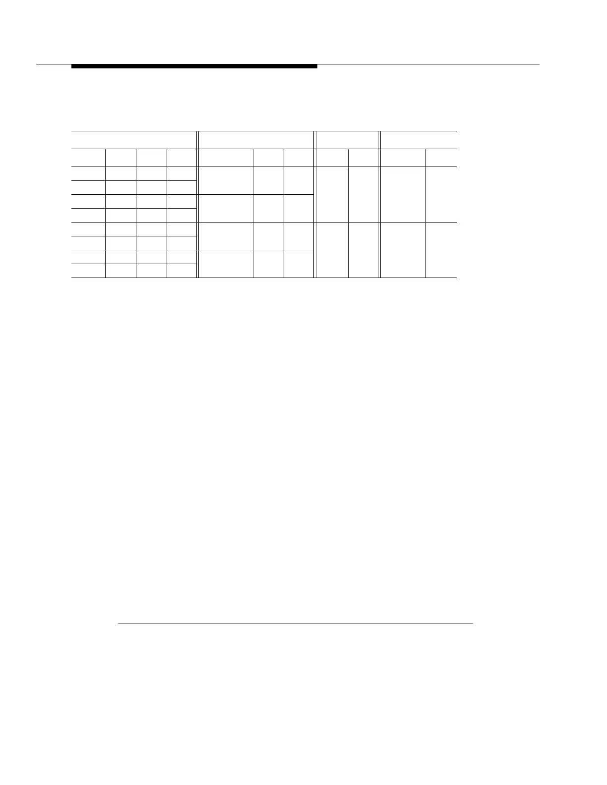
Figure 4 -7. BBG5 (SYSCTL) Option Switches (Sheet 2 of 5)
Switch 1 Settings
TBOS Display Number TBOS Backup Number CO/RT Remote TBOS
Value Sec 1 Sec 2 Sec 3 Value Sec 4 Sec 5 Value Sec 6 Value Sec 7
1 ON ON ON Primary ON ON RT OFF Enabled OFF
2 OFF ON ON
3 ON OFF ON Secondary OFF ON
4 OFF OFF ON
5 ON ON OFF Normal OFF OFF CO ON Disabled ON
6 OFF ON OFF
7 ON OFF OFF No-TBOS ON OFF
8 OFF OFF OFF