4-46
Issue 9 October 1998
363-206-204
Powering, Verification, and Circuit Pack Installation
2. If the shelf is connected to a DS1 clock (J37 on backplane) and the DS1 output (Sync
Out) will not be derived from the received OC-3 line for network timing distribution, set
the Timing Mode for "DS1 External, MULT OUT Mode".
3. If the shelf is located in an RT and DS1 output (Sync Out) will not be derived from the
received OC-3 line for network timing distributions, set the Timing Mode for
"Loop-Timed".
4. If the shelf DS1 timing output (Sync Out) is to be derived from the received OC-3 line for
network timing distribution, set the Timing Mode for "Loop-Timed, SYNC OUT Mode".
5. If the shelf is connected to a DS1 clock (J37 on backplane) and DS1 output (Sync Out) is
to be derived from the received OC-3 line for network timing distribution, set the Timing
Mode for "DS1 External, SYNC OUT Mode".
6. The pulse format (AMI or B8ZS) and frame format (superframe or extended superframe)
are set for the attributes of the external clock if "External" timing is selected. In the
absence of DS1 clock information set DS1 line code for AMI and Frame Format for
Superframe.
Note
s:
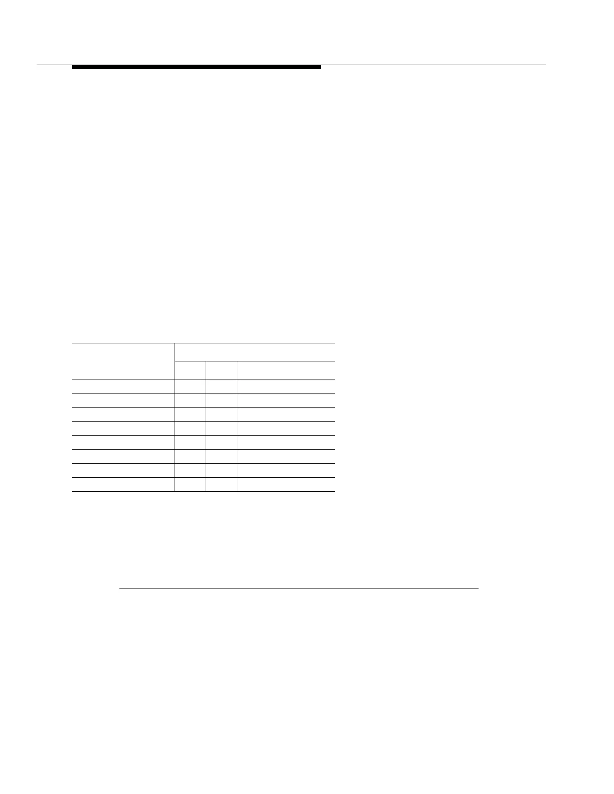
1. Equalization is set according to the length of the DS1 external timing cable, running from
J44 of the DDM-2000 OC-3 shelf to the timing reference when the BBF2B TGS is set for
SYNC OUT mode.
2. Distance in feet for 22-gauge PIC (ABAM) cable.
Figure 4 -14. BBF2B TGS Option Switches (Sheet 2 of 2)
Switch 2 Settings
Equalization (Notes)
Switch Settings
S2-1 S2-2 S2-3 (DS1 Output)
0’ to 131’ ON ON OFF
>131’ to 262’ ON OFF ON
>262’ to 393’ ON OFF OFF
>393’ to 524’ OFF ON ON
>524’ to 655’ OFF ON OFF
(Invalid) OFF OFF OFF
(Invalid) OFF OFF ON
(Invalid) ON ON ON