Manitowoc Published 07-19-16, Control # 249-01 1-91
2250 SERVICE/MAINTENANCE MANUAL INTRODUCTION
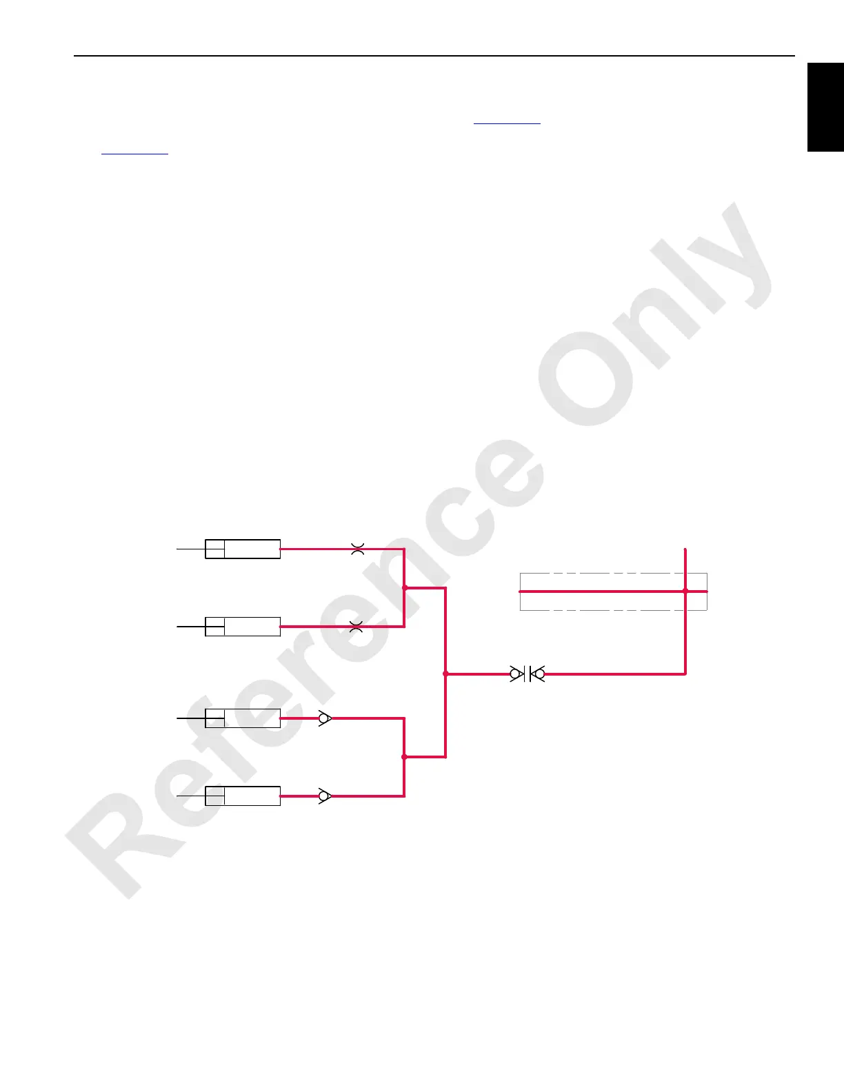
Mast Stop Raising And Boom Stop
Mast Stop Raising Cylinders
See Figure 1-59 for the following.
The mast stop raising cylinders pneumatically position the
physical mast stops. Once the physical mast stops are raised
at the assembly, the mast stop raising cylinders are pinned to
the physical mast stops. See Section 4 of MAX-ER 2000
Operator Manual for instructions on mast assembly/
disassembly.
When the engine is started, pressurized air at 8,2 to 9,1 bar
(120 to 132 psi) from the crane’s engine compressor
provides air to operate the mast stop raising cylinders. An air
line from the crane’s manifold goes to the quick disconnect at
the mast base. After the quick disconnect there is a tee that
splits, with one line going to the mast stop raising cylinders
on mast and the other line going to the boom stop cushion
cylinders on the boom butt. The mast stop raising cylinder
rods extend and push the mast stops to the working position.
The physical mast stop ends rest on the gantry pins. A fixed
restriction at the piston end of each cylinder acts as a
cylinder shock cushion.
Boom Stop Cushion Cylinders
See Figure 1-59 for the following.
The boom stop cushion cylinders pneumatically cushion the
boom against the mast when at or near maximum boom
angle.
When the engine is started, pressurized air at 8,2 to 9,1 bar
(120 to 132 psi) from the crane’s engine compressor
provides air to the boom stop cushion cylinders. An air line
from the crane’s manifold goes to the quick disconnect at the
mast base. After the quick disconnect there is a tee that
splits, with one line going to the mast stop raising cylinders
on mast and the other line going to the boom stop cushion
cylinders on the boom butt.
If the boom is raised to 80 degrees, the boom-stop cylinders
slow the boom’s opposite movement. Check valves prevent
compressed air from escaping the boom stop cylinders. Air
pressure increases in the boom stop cylinders, slowing the
boom before the boom stop struts contact the boom. At
approximately 90 degrees the boom-stop cylinders bottom
out and the boom physically stops. Orifices of the boom stop
cylinders act as shock absorbers for the lowered boom struts
when transporting the crane.
RM-15
From Main
Air Manifold
Manifold
Check
Valve
Check
Valve
Right Boom
Stop Cushion
Cylinder
Left Boom
Stop Cushion
Cylinder
Right Mast Stop
Raising Cylinder
Left Mast Stop
Raising Cylinder
Quick
Disconnect
Restriction
Restriction
FIGURE 1-59

 Loading...


