Manitowoc Published 07-19-16, Control # 249-01 5-25
2250 SERVICE/MAINTENANCE MANUAL HOISTS
ADJUSTING THE SLACK LINE SENSOR
General
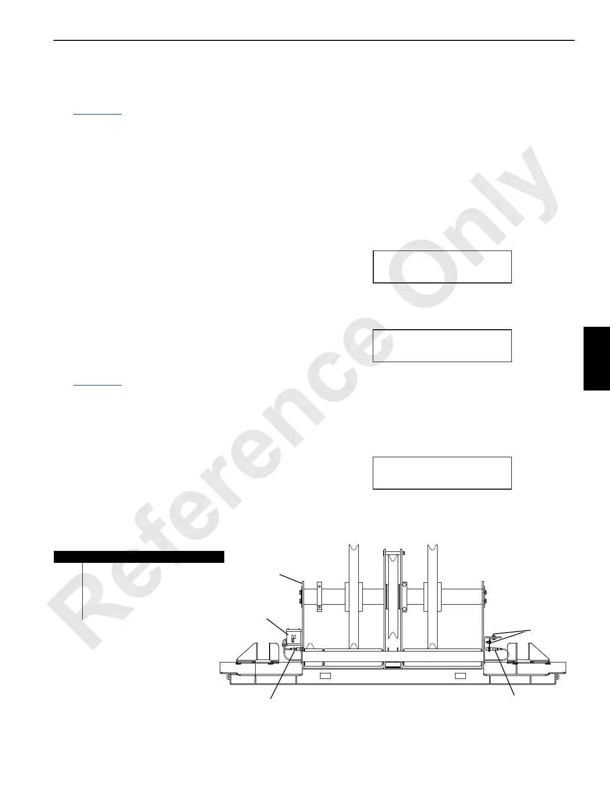
See Figure 5-23 for the following procedure.
A laser light sensor mounted on the boom butt wire rope
guide (1) detects a slack load line condition at either front or
rear drum. The rated capacity limiter (RCL) detects a slack
line condition at boom angles of 70 degrees and above if a
line pull of one half the calibrated weight ball is reached. In
either case, the operator is alerted as follows:
• The operating limit alert comes on (yellow light and
buzzer in the operator’s cab).
• The SLACK LINE INDICATOR message appears on the
display screen.
• The drum is inoperable in the DOWN direction.
To correct a slack line condition, haul in the load line on the
affected load drum. The operating limit alert goes off.
At least weekly, check the slack line sensor for correct
operation and clean the optical lens of the transmitter (3) and
receiver (4). The operating limit alert could be accidentally
activated if either lens is dirty.
Adjusting the Light Sensor
See Figure 5-23 for the following procedure.
Lower the boom onto blocking to service the slack line
sensor. The transmitter (3) mounted at the sensor junction
box (2) is fixed. Make all adjustments at the receiver (4).
1. Stop the crane engine and place the Run/Stop switch in
the RUN position.
2. Verify that the transmitter is emitting a light beam.
3. Loosen the adjusting screws and brackets (5) at the
receiver.
4. Position the receiver in line with the transmitter light
beam by moving the brackets in the slots.
NOTE: The yellow LED on the receiver turns on when the
light beam is received by the transmitter.
5. Tighten the screws when the light beam is correct.
6. If the above procedure does not correct the problem,
calibrate the slack line indicator.
Calibrating the Slack Line Indicator
To calibrate the slack line indicator, lower all load blocks/
weight balls to the ground. Leave a little slack line at the first
fall and proceed as follows.
1. Scroll through the diagnostics to the Slack Line
Calibration screen.
2. Confirm the screen to begin the calibration process.
The screen asks what load sheave is being used, 1
through 4.
3. To change an answer, use the Select switch.
4. To verify an answer is correct, press the Confirm switch
and move on to the next sheave.
After all four sheaves have been verified (YES or NO), the
controller starts to calibrate the load cells.
After the screen counts to 100%, calibration is complete.
SLACK LINE INDICATOR
CONFIRM TO BEGIN
FIGURE 5-20
SLACK LINE INDICATOR
SHEAVE 1 IN USE? YES
FIGURE 5-21
SLACK LINE INDICATOR
0% COMPLETE
FIGURE 5-22
A03999
Item Description
1 Boom Butt Wire Rope Guide
2 Sensor Junction Box
3 Transmitter
4Receiver
5 Adjusting Screw (qty 2) and Bracket
FIGURE 5-23
1
2
3
4
5

 Loading...


