Manitowoc Published 07-19-16, Control # 249-01 1-29
2250 SERVICE/MAINTENANCE MANUAL INTRODUCTION
Engine Controls
See the engine manufacturer’s manual for instructions.
The engine is started and stopped with the engine key
switch.
Engine rpm is controlled with the hand throttle or foot throttle.
The programmable controller (PC) and engine control
module (ECM) monitor engine information and display the
information on a digital screen.
The crane’s system speed depends on the engine’s speed
and the control handle’s movement in either direction from
the neutral position. The engine’s clutch lever for the pump
drive must be manually engaged for operation.
Use the engine stop push button only in an emergency as all
of the brakes apply and any function stops abruptly.
Three engine diagnostic lights are mounted on the front
console. See Power Train
Section 7 for diagnostic light
information.
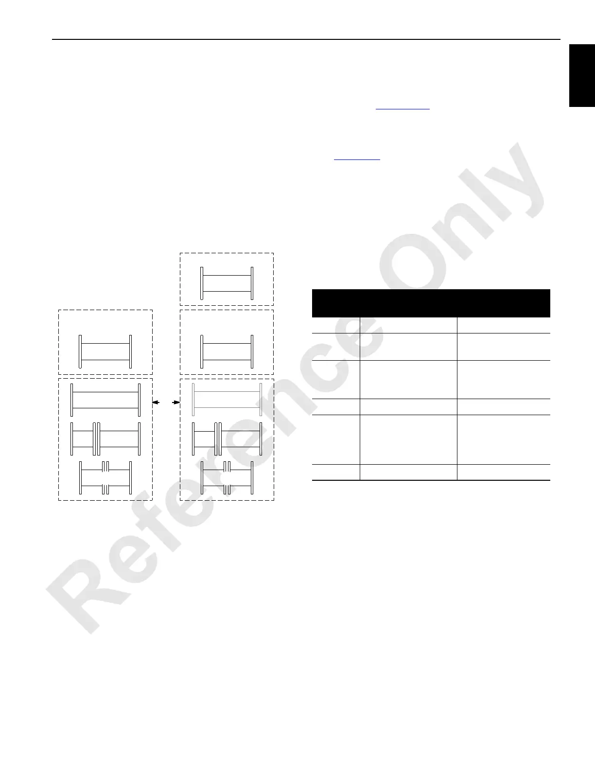
Drum Identification
See Figure 1-14 for the following.
The handle-to-load drum selection turns on a corresponding
numbered green light adjacent to the control handle on the
right console. See Operating Controls in Section 3 of the
Operator Manual for handle-to-drum identification and
selection.
Drum
Number
2250 MAX-ER 2000
1 Front Load Drum No Drum Available
2
Rear or Right Rear
Load Drum
Boom Hoist
3
Left Rear Load Drum
or
Mast Hoist (MAX-ER)
Rear Load Drum
(with luffing hoist)
4 Boom Hoist Mast Hoist
5 Luffing Hoist
Luffing Hoist or
Rear Load Drum or
Auxiliary Drum
(without luffing hoist)
9 — Front Load Drum
A645
OR
MAX-ER 2000 Attachment
2250
Drum on Front of
Adapter Frame
Drum on Front of
Adapter Frame
Drum in Boom Butt
No Drum Here
5
1
3
2
4
5
2
3
4
9
RF-07
FIGURE 1-14
 Loading...


