HOISTS 2250 SERVICE/MAINTENANCE MANUAL
5-8
Published 07-19-16, Control # 249-01
INSPECTING AND ADJUSTING THE DRUM
BRAKE
Description
Each drum brake consists of an external, contracting band-
type brake and two actuators. On single drum shafts, the
brake is mounted on the left end of the drum. On split drum
shafts, a brake is mounted on the outboard end of both
drums. An independent drum drive has two brakes, one
mounted on the left end of the drum shaft and the other
mounted on the right end.
Each actuator has two chambers that provide two separate
braking systems for each load drum as follows:
• The spring chamber provides a spring-applied, air-
released park brake. In the full power mode, the load
drum control automatically applies and releases the park
brake.
• Only one service chamber is used. It provides an air-
applied, spring-released working brake. Braking control
is variable, from fully applied to fully released, through
the use of a treadle valve.
The operator must be seated and the engine must be
running to operate the drum controls and park brakes during
inspection, adjustment, and overhaul procedures. The
drums are automatically parked and the handles are
inoperable when the operator is out of the seat or the engine
is off.
Inspecting and Adjusting the Brake
1. Inspect all pins and linkage for excessive wear. Replace
parts as required. Worn pins and linkage make it difficult
to obtain the proper drum-to-lining clearance.
2. Lubricate the pins in the linkage with a few drops of
engine oil. Lubricate the grease fittings. See Lubrication
Section 9 for more information.
3. Check the linings for excessive wear. Linings normally
wear faster at the dead end of the brake band. Check
this area first.
The brake lining is 12 mm (1/2 in) thick when new.
Replace the lining when the thinnest area has worn to
5mm (7/32in) thick.
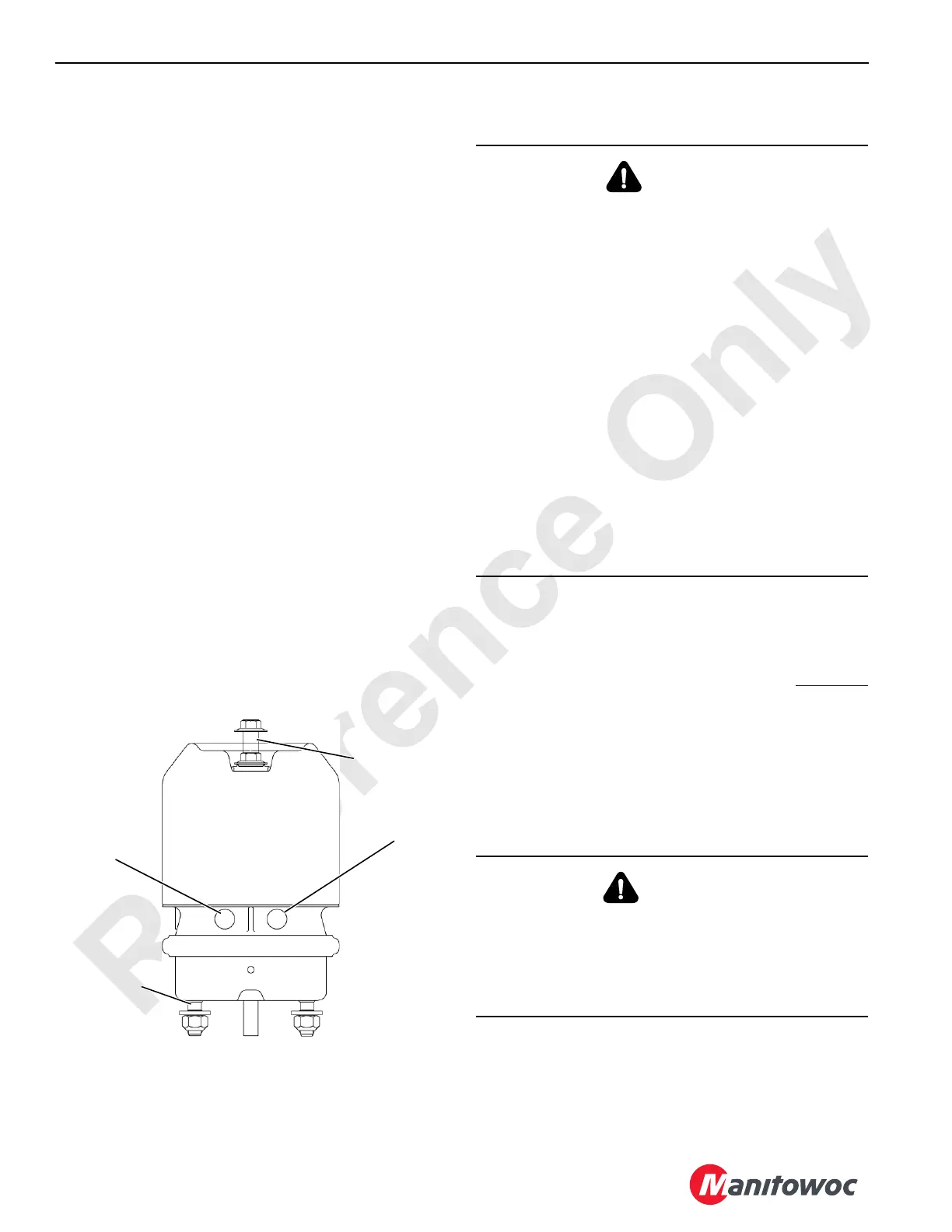
Mounting Studs
FIGURE 5-6
Service Brake Port
(working brake)
192789-2
Service Brake Port
(park brake)
Brake Release
(shown caged)
CAUTION
Moving Machinery Hazard!
It is necessary to rotate the load drum and apply and
release the drum park brake during inspection,
adjustment, and overhaul procedures. This creates a
condition in which, if care is not exercised, minor injury or
equipment damage may occur.
Drum brake inspection, adjustment, and overhaul
requires two people—one to operate the drum and brake
controls and one to perform the inspection, adjustment,
and overhaul procedures. Maintain constant
communication between the adjuster and operator so the
drum and brake are not operated while the adjuster is in
contact with moving parts.
Lower the load block or weight ball onto the ground so the
wire rope is slack on the drum being serviced.
• The adjuster shall stay clear of all moving parts while
the drum and brake are being operated.
• The operator shall not operate the drum or brake
controls until the adjuster is clear of moving parts.
WARNING
Falling Load Hazard!
Aftermarket brake linings may not provide the proper
brake torque. The brake could slip, allowing the load to
drop, resulting in death or serious injury.
Only use Manitowoc Cranes original equipment linings.

 Loading...


