Manitowoc Published 07-19-16, Control # 249-01 8-3
2250 SERVICE/MAINTENANCE MANUAL UNDERCARRIAGE
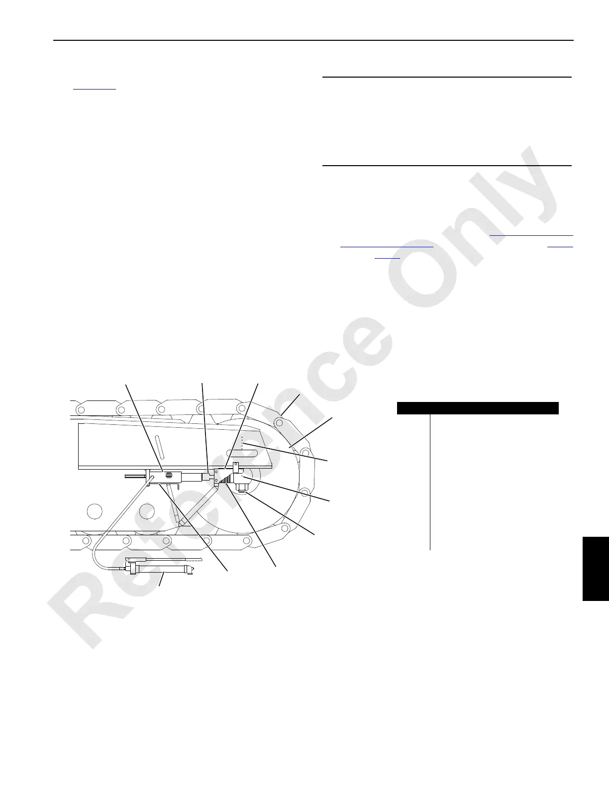
Adjusting the Tread Slack
See Figure 8-3 for the following procedure.
Adjust the tread slack at the front roller end of each crawler.
1. Thoroughly clean the crawler to be adjusted.
2. Loosen the two bolts (1) at the front roller end of the
crawler (1 bolt, each side).
3. Remove the cover (2) from each side of the crawler
frame.
4. Place the jack cylinder (3) on the support (4).
5. Using the hand pump (11), jack against the rod (5) an
equal amount on both sides of the crawler frame.
6. Add or remove an equal thickness of shims (6) on both
sides of the crawler frame.
7. Remove the jack cylinder.
8. Travel the crane forward to tighten the shims.
9. Verify that the dimension from center punch mark A (10)
in the shaft to center punch line B (9) in the crawler
frame is within 3 mm (1/8 in) of each other on both sides
of the crawler.
10. Check for proper adjustment (see Crawler Adjustment
Guideline on page 8-2) and readjust as required (step 4
through step 9).
11. Tighten the nuts on the bolts at the front roller to
2 712 Nm (2,000 lb-ft).
12. Install the cover on each side of the crawler frame.
NOTE: The extreme limit of crawler tread (7) adjustment is
when the bolts are tight against the front end of the
slots in the crawler frame. One crawler tread can
be removed when this limit is reached.
CAUTION
Excessive Part Wear!
Crawler parts will wear rapidly if they are not adjusted
properly.
Make sure the front roller (8) and the rear tumbler are
square with the crawler frame to within 3 mm (1/8 in).
FIGURE 8-3
Item Description
1 Bolt (qty 2)
2 Cover (qty 2)
3 Jack Cylinder
4 Support (qty 2)
5 Rod (qty 2)
6Shims—
3 mm (0.12 in) and
6 mm (0.25 in) Thick (
qty varies)
7 Crawler Tread
8 Front Roller
9 Center Punch Line B
10 Center Punch Mark A
11 Hand Pump
A1052
11
10
9
5
6
7
8
1
2
3
4
 Loading...


