HYDRAULIC AND AIR SYSTEMS 2250 SERVICE/MAINTENANCE MANUAL
2-28
Published 07-19-16, Control # 249-01
4. Wash all parts in soap and water and dry.
5. For the Type A filter, wash the element in alcohol and
blow it out from the inside with air. For the Type B filter,
discard the element.
6. Inspect all parts for damage and replace as necessary.
7. Use the diagram to reassemble the filter. Tighten all
threaded parts securely.
8. If disconnected, reconnect the air lines to the proper
ports of the filter. Use pipe-thread sealant or tape
sparingly and apply only to the male threads.
NOTE: The top of the Type A filter is marked IN and OUT
to identify the ports. Connect the line from the tank
to the IN port.
The top of the Type B filter has an arrow to identify
direction of flow. The arrow must point away from
the air tank.
9. Close all drain valves and open all shut-off valves.
10. Build air system pressure to the normal operating range
and check the filter for leaks.
Automatic Drain Valve Operation
NOTE: The automatic drain valve is not used on all filter
installations.
The automatic drain valve contains a float. When the liquid in
the valve body rises to the level of the float, the float rises to
open a needle valve. This action allows the liquid to drain. Air
pressure then re-seats the float, and the cycle repeats.
AIR SYSTEM DE-ICER MAINTENANCE
Operation
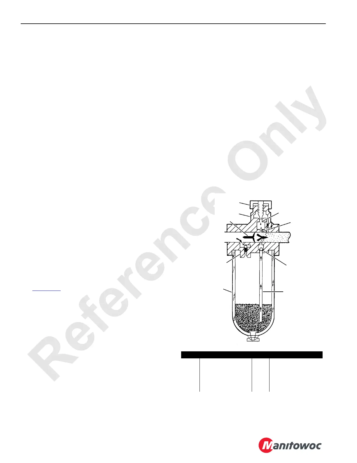
See Figure 2-32 for the following.
The air system de-icer meters antifreeze into the air line only
when there is air flow through the de-icer. Air flowing through
the de-icer passes around the flow sensor (1) to the
downstream system. Inlet pressure is admitted to the
reservoir (9) through the check (charge) valve (2). When air
is flowing, a small pressure drop occurs across the flow
sensor. The outlet (lower) pressure is sensed in the sight
feed dome (3) through the nozzle passage (4). This
establishes a pressure drop across the metering orifice (5),
and antifreeze at inlet pressure flows upward through the
siphon tube (6) into the sight feed dome, where it drips into
the nozzle passage and then into the de-icer throat. The
adjusting knob (7) controls the drip rate. antifreeze drops are
atomized by the high velocity air flowing past the flow sensor
and are carried downstream. The check ball (8) prevents
backflow of antifreeze into the reservoir during periods of no
flow.
The flow sensor functions as a variable restriction in the
throat of the de-icer to produce a pressure drop of up to
0,3 bar (5 psi) that is proportional to the rate of air flow
through the de-icer. These variations in outlet pressure,
sensed in the sight-feed dome, cause a similar variation in
the pressure drop across the metering orifice as a function of
air flow. Thus, for a given drip rate setting at some average
air flow, a lower air flow will cause a proportionally higher drip
rate.
The check (charge) valve (2) controls the rate of reservoir
pressurization and allows rapid de-pressurization for refilling
without shutting off the air pressure. When the antifreeze
plug is loosened, a bleed orifice is exposed, which
immediately reduces the reservoir pressure. This pressure
drop causes the charge valve to close and restrict air flow
into the reservoir to eliminate blow-back when adding
antifreeze. When the fill plug is replaced, the reservoir re-
pressurizes through the charge valve at a nominal rate. The
charge valve opens fully when the inlet pressure is reached.
S115
FIGURE 2-32
Item Description Item Description
1 Flow Sensor 6 Siphon Tube
2 Check (charge) Valve 7 Adjusting Knob
3 Sight Feed Dome 8 Check Ball
4 Nozzle Passage 9 Reservoir
5 Metering Orifice
In
Out
1
2
3
4
5
6
7
8
9

 Loading...


