Manitowoc Published 07-19-16, Control # 249-01 1-69
2250 SERVICE/MAINTENANCE MANUAL INTRODUCTION
Hydraulic Quick Disconnect
General
A self-contained hydraulic system makes the mechanical
connections between the adapter frame and the rotating bed
hydraulic lines during assembly/disassembly.
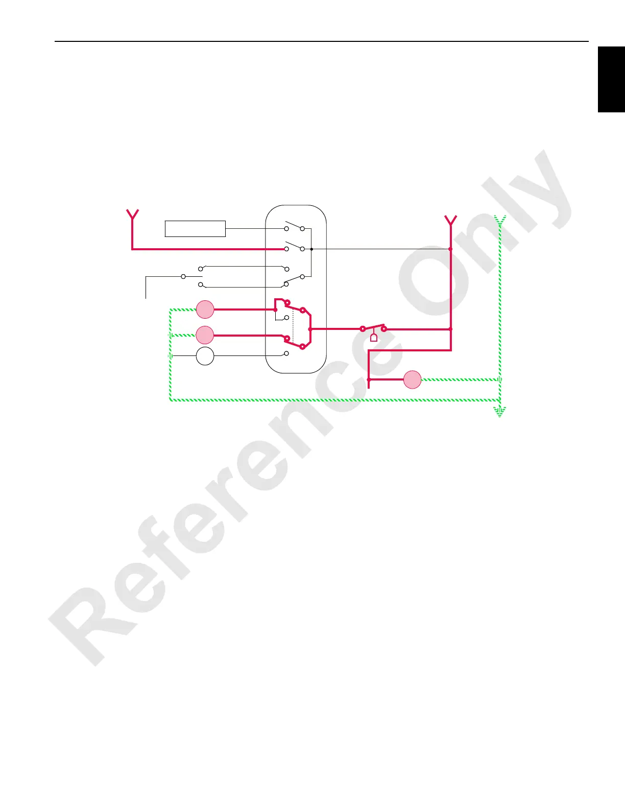
When the cab power switch is ON and the engine fluid
pressure switch is closed (engine not running), power is
available to the hydraulic quick disconnect switch at the
remote start junction box on the right side of the rotating bed.
The hydraulic quick disconnect is operational after the
following connections are made.
1. Connect the boom stop electrical cable from the rotating
bed to the junction box plug and couplers on the right
side of the adapter frame.
2. Connect the luffing jib pawl air lines from the rotating bed
to the junction box plug and couplers on the right side of
the adapter frame.
Hydraulic Quick Disconnect Engage
When the hydraulic quick disconnect switch is moved to the
engage position, an output signal is sent to engage the
hydraulic solenoid HS-33 and hydraulic disconnect relay
(HDR). The relay sends an output signal to enable the
hydraulic quick disconnect motor in the engage direction.
When the hydraulic solenoid HS-33 is enabled, the fluid from
the motor flows past the relief valve that limits system
pressure to 21 bar (300 psi), through the solenoid valve to
the piston end of the frame cylinder.
The frame cylinder extends the rotating beds coupling plate
and sleeve plates together toward the adapter frame
coupling plate. The hydraulic quick disconnect closes as the
fluid from the rod end returns to the tank through the
sequence valve and then through solenoid HS-33.
Fluid also flows to the piston end of each coupling cylinder.
Fluid from each coupling cylinder rod end flows back to the
tank through solenoid HS-33. Coupling cylinders extend to
close the quick disconnect, completing hydraulic line
coupling between the rotating bed and the adapter frame.
Hydraulic Quick Disconnect Disengage
When the hydraulic quick disconnect switch is moved to the
disengage position, an output signal is sent to disengage the
hydraulic solenoid HS-34 and the hydraulic disconnect relay
(HDR). The relay sends an output signal to enable the
hydraulic quick disconnect motor in the disengage direction.
When the hydraulic solenoid HS-34 is enabled, the fluid from
the motor flows past the relief valve that limits system
pressure to 21 bar (300 psi).
Fluid from the solenoid valve flows to the rod end of the side
of each coupling cylinder and through the sequence valve to
the rod end of the main cylinder. A check valve blocks flow to
the main cylinder. Then the coupling cylinders retract the
sleeve plate first to unlock the couplings. Then at 14 bar
(200 psi), the sequence valve opens to allow flow to the
frame cylinder. The frame cylinder retracts, separating the
rotating beds coupling plate from the adapter frames
coupling plate.
Hydraulic quick disconnect opens, separating the coupling of
hydraulic lines between the rotating bed and the adapter
frame as the fluid from the piston end of the cylinders returns
to the tank through solenoid HS-34.
7
Engage
Ground
Programmable
Controller
68R
7
3
START
RUN/STOP
Cab
Power
Remote Start
Junction Box
RF-43
RUN/STOP
1500 rpm
5DA
3
Oil Pressure
Hydraulic
Disconnect
Disable
0
HS
34
HDR
HS
33
Disengage
Hydraulic
Motor
K1
FIGURE 1-42
 Loading...


